Working in the line table or in the document window (graphic)
Working in the line table or document window:
 document window is enabled.
- The coupe de base is displayed graphically.
- 1
- To create a lined shape based on the displayed rectangle in the ribbon Élaboration de la coupe under Caractéristiques, click the Yableau des lignes button.
- or -
Use the graphic displayed in the document window. - 2
- Create the desired shape lines.
Example: Lined shape for the structure pattern
|
Basic Shape: Front |
|
|
 : You may use the method you prefer as both views are always adjusted to each other.
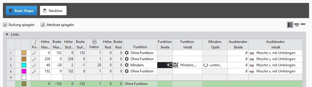
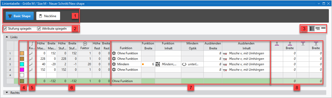
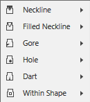
About the Line Table
|
| ||||
|
1 |
| |||
|
2 |
|
Inverser les escaliers en miroir |
Creating a symmetric shape of shape element
| |
|
|
Faire une inversion miroir des attributs |
Attribute changes carried out in the line table at the left and right. | ||
|
|
Do not mirror attributes |
Attribute changes are carried out in the line table at the left or at the right. | ||
|
|
Do not mirror stepping |
Creating an asymmetric shape / shape element
| ||
|
3 |
|
Afficher toutes les propriétés | ||
|
|
Afficher les sous-lignes | |||
|
|
Masquer les sous-lignes | |||
|
4 |
Display color for main lines and sub-lines of a selected line in the | |||
|
5 |
|
Courbe |
| |
|
6 |
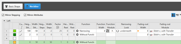
Columns for entering the values for the lines of the lined shape in the input format
| |||
|
7 |
Columns for the input of line attributes
| |||
|
8 |
Specification for working with PTS (NPJ) for one line (shape edge)
| |||


 factor, height of rest and width of rest is calculated.
Insert shape line in a shape element:
: The shape lines are inserted symmetrically with both methods by default.
-
In the Line Table:
Entry of a positive value: Widening and upwards
Entry of a negative value: Narrowing and down - Enter the desired values in the last table line with the * symbol. When confirming the input with the Enter key a new table line is inserted.
- Select a row, open the context menu with RMB and select Ajouter une ligne principale.
- Select a row, open the context menu with RMB and select Ajouter une ligne avant.
- or -
Select Ajouter une ligne après.
: Only in the line table it is possible to create an asymmetrical line shape by deactivating  .
.
-
In document window
- Position the cursor on a line of the displayed graphic -> open the context menu with RMB and select -> Insérer la ligne de coupe .
Create New Shape Element:
- In the Line Table
- Position the cursor in the area next to the
 coupe de base button, open the context menu by RMB and select Ajouter un nouvel élément de coupe....
 -
In document window
- Position the cursor in the document window of the graphic, open the context menu with the RMB and select Ajouter un nouvel élément de coupe....
- 1
- In the selection menu select the desired symmetric / asymmetric shape element.
- 2
- Edit the shape lines of the created shape element the same way as the basic shape.
- The newly created shape element is displayed in the graphic and in the line table as well.
|
Shape Element Type: Neckline symmetric |
|
|
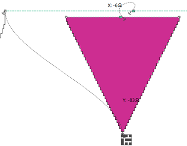
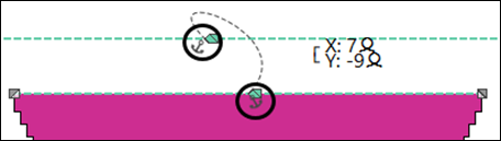
Positioning of a shape element in the basic shape
:
Every shape element gets a link (anchor) to a shape point in the basic shape during its creation.
- A basic shape is created with a shape element for the neckline.
- 1
- Position the cursor in the shape element.
- 2
- Reposition the shape element with the LMB pressed.
- or -
Move the shape with the arrow keys of the keyboard.
- or -
Open the coordinate display in the shape element double-clicking LMB and enter values. - The anchor point becomes visible with its X and Y coordinates in the Encolure shape element.
- 3
- Change the positioning if necessary.
Possibilities for editing an anchor via the context menu
|
| |
|
|
Tool window for manually changing the values of X and Y coordinates. |
|
Diviser l'ancre |
Ungroup the grouped anchor in one anchor for X coordinate and one for Y coordinate, to be able to anchor one anchor with another shape element.
|