Step 3: Set docking points
Open the graphic display of the shape
- 1
- Open the Shape View with the
 button in the toolbar of the ShapeWizard.
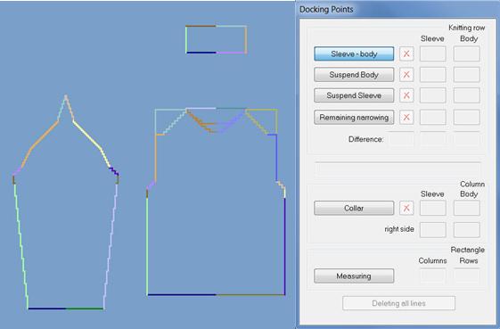
Set docking points
- 1
- Select Docking point.
- 2
- Place the cursor at the edge of a shape part and hold down the left mouse button.
- 3
- Move the cursor to the edge of the connecting shape part and specify the end position of the connection, release the left mouse button.
- 4
- To remove an existing connection, press the
 button.
 - 5
- With the + and - keys in the numeric keypad the shape view can be zoomed in and zoomed out.
Needed docking points
|
Docking points |
Function |
|---|---|
|
Sleeve - body |
The first docking point references the position of the sleeve in relation to the body. |
|
Remaining narrowing |
Connects the remaining narrowing of the sleeve with the shoulder gore of the body. |
|
Collar |
The collar element is set to corresponding width by the connection. |
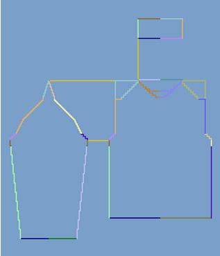
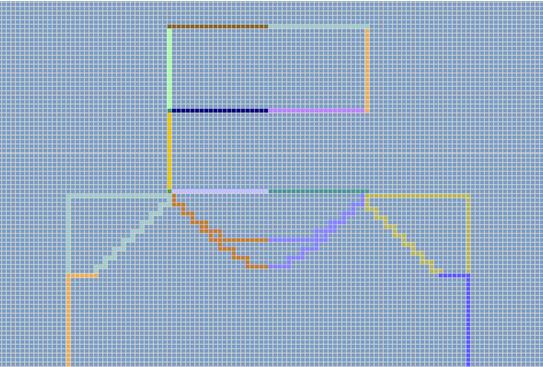
Docking point sleeve - body
- No widening or narrowing within the sleeve body connection.
- 1
- Define the Sleeve - Body docking point in the Docking point.dialog box.
- 2
- Set the connection line from the sleeve to the body.
- The sleeve body connection determines the position of all Areas to each other.
- The knitting sequence for the sleeve-body connection is entered until the connection line.
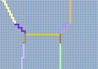
Docking point for remaining narrowing
- 1
- Define the Remaining narrowing docking point in the Docking point dialog box.
- 2
- Determine the connection line from the remaining narrowing of the sleeve to the end of the shoulder gore body.
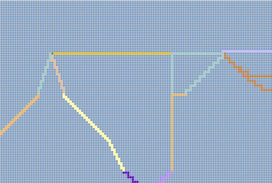
Docking point Collar
- 1
- Define the Collar docking point in the Docking point dialog box.
- 2
- Set the connection line from the left collar start to the left edge end line body.
To the next step 4: Generate k&w file