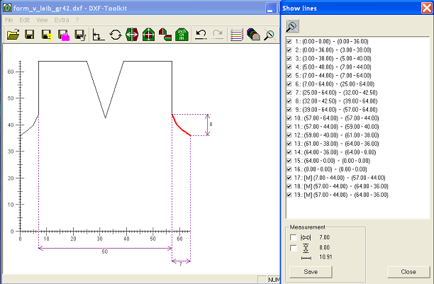
Define Measures in the DXF-Toolkit
In the DXF-Toolkit you can define measures which can be displayed in the graphic as horizontal and/or vertical measurement arrows.
By this you can define control measures which are displayed in the graphic and can be handed over as print out.
(In order to print out a graphic of the DXF-Toolkit you can copy it into the paste buffer via the Alt+Print shortcut and paste it as picture in a corresponding program e. g. Word or Paint.)
Therefore you can select one or several lines in the Show Lines dialog box. The measures between the starting point and the ending point of the last selected line are shown in the dialog box.
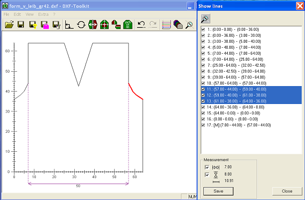
By activating the checkboxes in the Measurement section and Save this measure is adopted as measuring line in the DXF file (in the measuring lines layer). A measuring line is marked with a [M] in the line table. You can toggle on/off measuring lines as well as shape lines by activating or deactivating the checkbox of the corresponding line.