Creating shape
I. Generate shape:
- 1
- Call up the M1plus Shape Editor via the / menu.
- The dialog box will be opened.
- 2
- Open an existing shape via the / menu.
- 3
- Example:D:\Stoll\M1plus\Versions\Form\2_set-in-front-v-neck-38.shv.
- or -
Create a new shape via the button.
 - 4
- Create the element for the basic element.
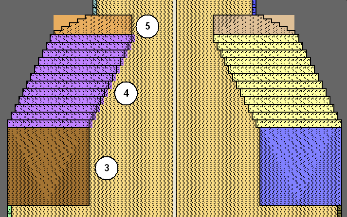
Basic element Front Left Edge:
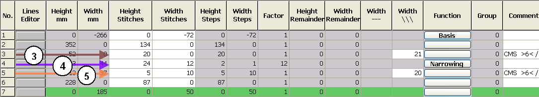
- 5
|
Edge no. |
Height of stitches |
Width of stitches |
Height of steps |
Width of steps |
|---|---|---|---|---|
|
No. 5 |
20 |
0 |
20 |
0 |
|
No. 4 |
24 |
12 |
2 |
1 |
|
No. 2 |
5 |
10 |
5 |
10 |
- In order to simplify the shape creation some examples for modules for the 1x1 selvedge in the shape view are shown.
- 6
- Deactivate the checkbox and create the right side table.
- 7
- Create element for the opening.
Element Neck opening:
- 8
- Select the basic element and set the Distance of the shape halves to 1.
- The V-neck will be started with one needle.
- 9
- Select the Neck opening element.
- 10
- Click on the
 button in the toolbar.
- The Left lines No.: 1 dialog box is opened.
- 11
- Under module allocation click on Structure double jersey and in the selection list select Structure double jersey V1 for the start of the V-neck.
- 12
- Define the horizontal and vertical position via .
- 13
- Allocate fade-out modules to the edges of the basic elements and to the element Neck opening.
- 14
- Use the fade-out modules from the Module Explorer of Database.
- or -
Generate your own fade-out modules.