Step by Step to Pattern-1
- A pattern project with one pattern and the desired settings is created.
- 1
- Work with the following drawing tools:
- Group Drawing Tools :
-
 Pencil (V)
 -
 Line (B)
 -
 Rectangle (N)
 -
Without the selection of a pattern color - Yarn Color:
A selection is generated.
While drawing with drawing tools without the selection of a pattern color, a
selection is generated.
It can be deleted with the shortcut Ctrl+D.
-
With the selection of a pattern color - Yarn Color:
The yarn color is drawn into the basic pattern.
- Deleting all cursor attributes: Key ESC
- Deleting of individual cursor attributes with X via the corresponding attribute

|
|
|
For drawing the design pattern, with it several yarn carriers may be necessary for each yarn color.
|


- 2
- Change the width and height of the pattern.
- Group Modify :
- Zoom (function button Z)
- Delete / insert row(s) / column(s)

- Select row(s) / column(s) and insert / delete
- 3
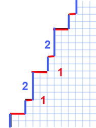
- Draw-in colored stripes in any yarn color from row 27 at the height of 18 rows.
- 4
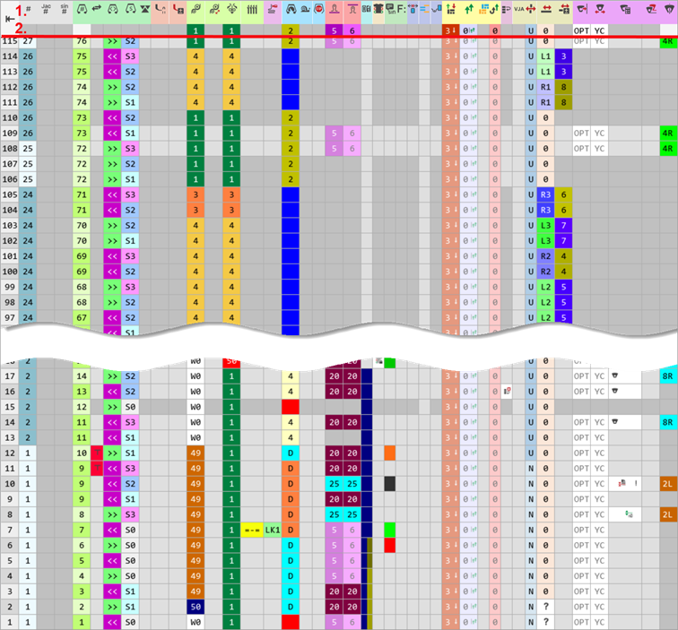
- Adjust the view of the control columns.
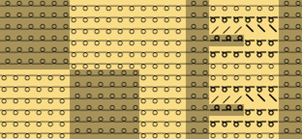
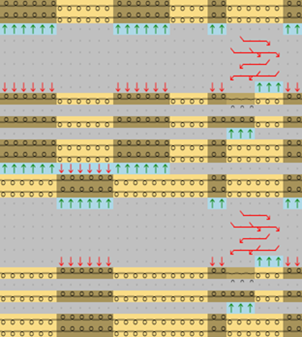
- In the design pattern (before technical processing)
- In the technical pattern (after technical processing)
Displaying the control columns in the document window
- The control columns can be displayed in every document window.
-
 Show Control Columns (TAB)
 -
 Hide Control Columns (TAB)
 - The control columns are divided into colored groups.
View Options of the Control Columns:
- Show Used Control Columns
- Hide All Control Columns
- Show All Control Columns
- User-defined Control Columns
- Project Layout
- User Layout
Overview of all possible control columns after technical processing
|
| |||
|
| |||
|
| |||
|
Table header: |
1 . |
Symbols to identify control columns | |
|
2. |
Default settings from global file STOLL for the respective control column with a new pattern project
| ||
|
| |||
|
Group 1 |
|
Pattern Row |
Display the consecutive numbering of the pattern rows.
|
|
|
Jacquard Line Number |
Display the Jacquard line number.
| |
|
|
Sintral Line Number |
Display the Sintral line number.
| |
|
Group 2 |
|
Number of Stroke |
Display stroke number
|
|
|
Stroke |
Specifications for defining the carriage stroke | |
|
|
Carriage Direction |
Presets of the carriage direction
| |
|
|
System |
Presets of the use of knitting systems
| |
|
|
System Function |
With the use of special cams
| |
|
Group 3 |
|
Main Take-down (WMF) |
Presets for comb, main take-down and auxiliary take-down |
|
|
Open Main Take-down (=W= / =C=) | ||
|
|
Auxiliary Take-down (W+F) | ||
|
|
Comb | ||
|
Group 4 |
|
Control of Collecting Area (LK / LW) |
Presets for the control of the collecting area
|
|
|
Fabric Sensor (WS) |
Specifications for the fabric sensors
| |
|
Group 5 |
|
Speed (MSEC) |
Presets for carriage speed |
|
|
Machine Slow (ML) | ||
|
|
Machine Stop (MS) | ||
|
Group 6 |
|
Front Stitch Length (NPv) |
Presets for the stitch length on front and rear needle bed |
|
|
Rear Stitch Length (NP^) | ||
|
Group 7 |
|
Cycle (RS) |
Specifications for cycles for length control
|
|
Group 8 |
|
Border Fixation |
Presets for the border fixation |
|
Group 9 |
|
Sintral Instruction / PRINT |
Presets for the Sintral and PRINT command |
|
|
Function call (F:) |
Presets for function calls and additional commands | |
|
Group 10 |
|
Knitting-out |
Presets for knitting-out all the yarn carriers of a common row |
|
|
Color Arrangement |
Color entry for Color Arrangements in use | |
|
|
Intarsia Binding |
Presets for the tuck binding with intarsia / gore in a common row | |
|
Group 11 |
|
Transfer Surrounding |
Preset for transferring of the whole pattern or in a defined areas |
|
|
Multi-system Transferring | ||
|
|
Module Arrangement |
Color entry for Module Arrangements in use | |
|
|
Cast-off and Transfer |
Preset for combining transferring and casting-off in a common technical row of the whole pattern or in a defined areas | |
|
Group 12 |
|
Sorting Technical Rows |
Specifications for
|
|
Group 13 |
|
Knitting with racked beds (VJA^) |
Specifications for jacquard selection at the rear needle bed |
|
|
Racking (VN, VU, V#) |
Preset of racking type
| |
|
|
Racking Value |
Specification of the racking step for the rear needle bed | |
|
|
Racking Correction (VCI) |
Preset for racking corrections | |
|
Group 14 |
|
Yarn carrier staggering (YD)/(YDI) |
Presets of yarn carrier staggering on the fabric selvedge for Setup |
|
|
Yarn Carrier Correction (YC / YCI) |
Presets of yarn carrier corrections for Setup | |
|
|
Yarn Carrier Presettings |
Specifications for
| |
|
|
Yarn Carriers |
Column for display of all relevant yarn carrier data after | |


Two modes to enter data in the control columns:
In the Home ribbon under Drawing.
-
One Click

Press LMB at start position and hold it until the end position. -
Double Click

Click and release LMB at start position and click it again at the end position.
Two modes to delete data in the control columns:
In the Home ribbon under Fill.
- Delete All from Control Column (except racking)
 Delete
 - All Control Columns to Default
 Default
The procedure for multiple entries in control columns:
- Cycle (RS)
- Yarn Carrier Presettings
- Yarn Carrier Parking
Add an entry to an existing entry:
- Add

With the Ctrl key - Select the desired location in the menu:
- Set cursor to the start position.
- Press the CTRL key.
- Press LMB and hold it until the end position.
- Release the left mouse button.
- Add

With the Ctrl key - Select the desired location in the menu:
- Set cursor to the start position.
- Press the CTRL key.
- Click left mouse button.
- Draw the cursor to the end position.
- Click left mouse button again.
Delete Entry:
- Delete
With the CTRL + ALT key - Set cursor to the start position.
- Press LMB and hold it until the end position.
- Release the left mouse button.
- Delete
With the CTRL + ALT key - Select the desired location in the menu:
- Set cursor to the start position.
- Press the CTRL + ALT keys.
- Click left mouse button.
- Draw the cursor to the end position.
- Click left mouse button again.
Selecting Control Columns
- 1
- Position the cursor in the header of the control columns and press the right mouse button to open the context menu.
- The context menu appears.
- 2
- Select the desired control columns in the context menu via User-defined Control Columns.
- 3
- Open the context menu with RMB.
- 4
- Select Save Appearance of Design Patterns as Default in the menu.
- The setting will be saved and loaded when opening a design pattern.
Viewing Options of Control Columns
|
User-defined Control Columns |
Adding or closing the desired control columns in the selection list |
|
Show Used Control Columns |
Display of the control columns used in the pattern |
|
Show All Control Columns |
Display of all control columns |
|
Hide All Control Columns |
Hide the display of control columns |
|
Freeze this Control Column (double-click) |
Freezed control columns keep visible when hiding control columns
|
|
Hide this Control Column |
Hide control columns at the cursor position. |
|
Hide this Group |
Hide all control columns allocated to a group. |
|
Save Appearance of Design Patterns as Default |
Save the selected control columns as user defined default for editing the design pattern. |
|
Load Default Appearance of Design Patterns |
Restore the customized default for editing the design pattern. |
|
Reset Appearance of Design Patterns to STOLL Default |
Restore the saved STOLL default setting. |
 : Unfreezing by
 - 5
- Change the following pattern parameters using the control column in the colored stripe:
- Stitch Length
- 1
- Position the cursor on the desired
 or
or  control column.
 - 2
- Open the context menu with RMB and select Show in Table .
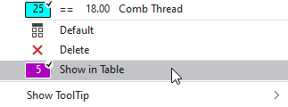
- or -
Select directly from the list of the Favorites. - The Pattern Parameters
dialog box appears.
- 3
- Open the Default tab.
- or -
Open the User tab. - 4
- Select the desired existing entry from the tables.
- or -
In the User tab position the cursor in the first column and select Add Table Row... in the context menu. - New entry is added at the end of the table.
- 5
- Make the desired presettings for the entries in use:
- Define NP index.
- Change Color.
- Enter NP value.
- Enter the description.
- 6
- In the desired area of the control column enter the color of the stitch length.
Change the specifications for the stitch lengths in the pattern:
- See and modify the default settings for the stitch lengths in the
 Design Pattern.
 - The Front Stitch Length (NPv) / Rear Stitch Length (NP^) control columns appear.
- 1
- Open the existing Pattern Project and save it with a new name via the File / Save As menu.
- or -
Create new Pattern Project with an individual pattern. - 2
- Set the cursor to the Front Stitch Length (NPv) / Rear Stitch Length (NP^) control columns of the Design Pattern document window and click the RMB.
- or -
Open the Stitch Length (NP) context menu in the second row of the table header containing the default settings. - The stitch lengths context menu appears.
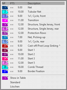
- The stitch lengths used in the pattern are displayed and are marked by the
 symbol.
 - The entries marked as favorites in the
 Stitch Length (NP) / Default tab under the Stitch Length section of the Pattern Parameters
tool window are displayed.
Stitch Length (NP) / Default tab under the Stitch Length section of the Pattern Parameters
tool window are displayed.
- 3
- Select the desired stitch length and enter it in the control column.
- or -
Fill a selection.
Notice:
The stitch lengths shown in the context menu correspond to the table in thePattern Parameters
tool window under the Stitch Length section of the Stitch Length (NP) / User
tab.
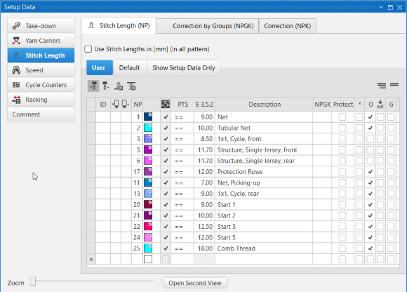
Open stitch length tab and select or change an entry:
-
Design Pattern is selected.
- 1
- Select
 Pattern Parameters
in the Home ribbon at Parameter.
Pattern Parameters
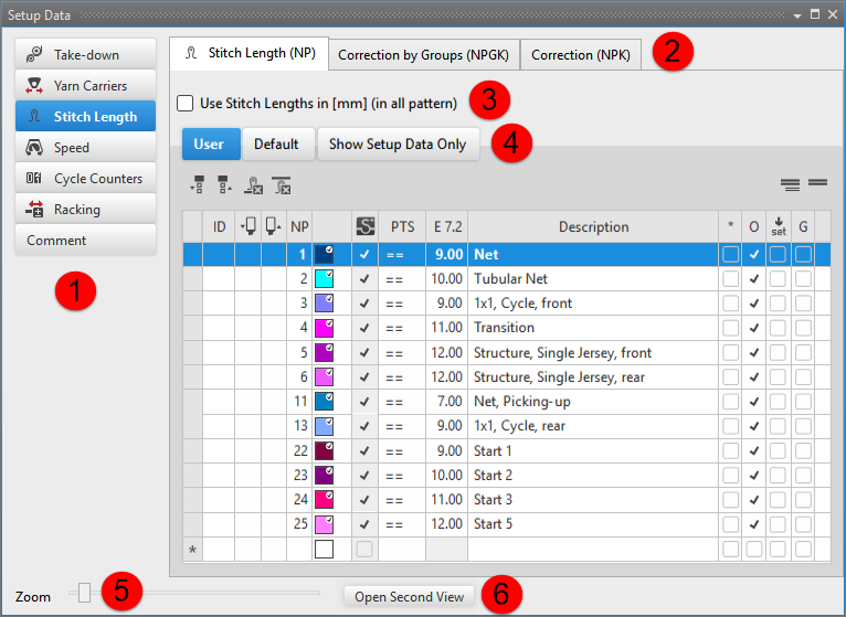
in the Home ribbon at Parameter. - The Pattern Parameters tool window appears.
|
| |||
|
1 |
All sections of Machine Parameters appear in Setup | ||
|
2 |
Tabs for additional machine parameters | ||
|
3 |
|
Use stitch length values in the STOLL default unit | |
|
|
Use stitch length values in millimeters | ||
|
4 |
Tabs | ||
|
User |
| ||
|
Default |
All the stitch lengths of the STOLL template | ||
|
Show Setup Data Only |
All the stitch lengths used in the pattern
| ||
|
5 |
Zoom |
Zoom in or out | |
|
6 |
Open Second View |
Opening an additional Pattern Parameters tool window. | |

- 2
- Select the Stitch Length section.
- 3
- Select the Stitch Length (NP) / Default tab.
- 4
- Select the desired stitch length in the
 or
or  column of the table and insert it in the control column.
-
Front Stitch Length (NPv)
Click the stitch length in the column. -
Rear Stitch Length (NP^)
Click the stitch length in the column. -
Front Stitch Length (NPv) and Rear Stitch Length (NP^)
Click the stitch lengths with the CTRL key in the and columns.
 The default settings in the control columns of these design rows will be overwritten.
Options in the toolbar
|
|
Selecting the default value to enter in the |
|
|
Selecting the default value to enter in the |
|
|
Deleting an entry in the |
|
|
Deleting an entry in the |
|
|
Show Pattern-related Values |
|
|
Hide Pattern-related Values |


Column labels of the stitch length tool window
|
Column |
Display |
|---|---|
|
ID / IDv / ID^ |
Consecutive numbering and sorting of the entries |
|
|
Selecting stitch length for the front needle bed to enter it into the control column and as PTS into the pattern |
|
|
Selecting stitch length for the rear needle bed to enter it into the control column and as PTS into the pattern |
|
NP |
Input and display of the index for the indirect (NPn=1-500) or direct (D) stitch length allocation |
|
Colors |
Display of colors to enter in the control columns |
|
PTS |
Specification for NPJ or PTS (Power Tension Setting). |
|
Gauge E |
List of stitch length values depending on the gauges of the selected machine |
|
Column |
Display | |
|---|---|---|
|
Description |
Comment on the use of the entry. | |
|
* |
|
Entry is not defined as favorite, meaning the entry is only within the Default table available. |
|
|
Entry is defined as favorite, meaning the entry is available within the User table or directly via the context menu of the control columns. | |
|
O |
|
Value cannot be overwritten (Overwrite) by a value of another table. |
|
|
Value can be overwritten (Overwrite) by a value of another table. (Default) | |
|
|
|
The entry will not be applied to the Setup data
|
|
|
The entry will be applied to the Setup data.
| |
|
G |
|
All settings of the Default or User
table are STOLL defaults (STOLL Template).
|
|
|
These settings of the Default or User
table are now User Standards (User-Template)
| |

Specify the favorites:
-
Design Pattern is selected.
- 1
- Open the Pattern Parameters tool window.
- 2
- Select the Stitch Length section.
- 3
- Select the Stitch Length (NP) / Default tab.
- 4
- Mark the desired entry in the column
 .
. - 5
- Close the tool window with
 .
.
- The selected entry will be displayed in the context menu and can be inserted in the design pattern for the front or rear stitch length.
Add a new entry in the stitch length tab:
 : New entries can only be added in the User
tab.
: New entries can only be added in the User
tab.
-
Design Pattern is selected.
- 1
- Open the Pattern Parameters tool window.
- 2
- Select the Stitch Length section.
- 3
- Select the Stitch Length (NP) / User
tab.
- 4
- Set the cursor in the left table column to the row.
- 5
- Call up the Add Table Row... context menu.
- A new entry will be added at the end of the table.
- 6
- Make the desired specifications in the columns of the new entry.
- 7
- Close the table with .
- Changes are saved to the table and are available in the project for each order and for all of its individual patterns.
: The changes will be saved to the *.spf file when saving the project.
Add entry of the Stitch Lengths (NP) tab to the pattern:
-
Design Pattern is selected.
- The control columns for Front Stitch Length and Rear Stitch Length are displayed.
- 1
- Open the Pattern Parameters tool window.
- 2
- Select the Stitch Length section.
- 3
- Select the Stitch Length (NP) / User
tab.
- 4
- Select the desired stitch length in the or column:
- Entry in the control column:
Click on the stitch length in the column. - Entry in the control column:
Click on the stitch length in the column. - Entry in the and control column
Click on the stitch lengths with the CTRL key in the and columns.
- 5
- Enter the stitch length in the control column.
- 6
- If necessary, change more pattern parameters, e.g. in the colored stripe, via the control columns:
-
Main Take-down
:
Create new WMF index in the Setup table and enter it into the control column. : WM min /WM max , N min / N max is displayed after technical processing in the Setup table according to the pattern width.
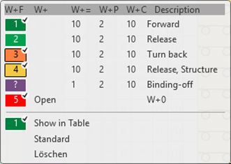
Change the specifications for the main take-down in the pattern:
- You see and change the default settings for the main take-down in the Design Pattern .
- The
 Main Take-down (WMF) control column is displayed.
- 1
- Open the existing Pattern Project and save it with a new name via the File / Save As menu.
- or -
Create new Pattern Project with an individual pattern. - 2
- In the document window Design Pattern, position the cursor on the Main Take-down (WMF) control column and click the RMB.
- or -
Open the context menu in the second row of the table header containing the default settings with RMB. - The context menu for the Main Take-down (WMF) appears.
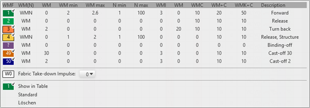
- The fabric take-down functions (WMF) used in the pattern are displayed and are marked by the symbol.
- The entries marked as favorites in the Main Take-down (WMF / WBF) / Default tab under the Take-down section of the Pattern Parameters
tool window are displayed.
- 3
- Select the desired main take-down value and enter it in the control column.
- or -
Fill a selection.
: The main take-down values (WMF) displayed in the context menu correspond to the table in the Pattern Parameters
tool window in the Main Take-down (WMF) section of the User
tab.
Select an entry of the Main Take-down (WMF) tool window and change it:
-
Design Pattern is selected.
- The Main Take-down (WMF) control column is displayed.
- 1
- Open the Pattern Parameters
tool window.
Home ribbon -> Tool Windows
  -> Pattern Parameters
selection menu
-> Pattern Parameters
selection menu
- or -
Parameters ribbon group-> Pattern Parameters
. - The Pattern Parameters
tool window appears.
- 2
- Select the Take-down section.
- 3
-
Main Take-down (WMF) / Default tab
- or -
Select User . - 4
- Select the desired main take-down value in the
 column and enter it in the control column.
- The default setting in the control column will be overwritten in these design rows.
Options in the toolbar
|
|
Selecting the default value to enter in the control column | |
|
|
Deleting an entry in the control column | |
|
WMF |
|
Hide the display of the columns wit the main take-down values for the Multiflex take-down |
|
|
Show the display of the columns wit the main take-down values for the Multiflex take-down | |
|
WBF |
|
Hide the display of the columns wit the take-down values for the belt take-down |
|
|
Show the display of the columns wit the take-down values for the belt take-down | |
|
|
Show Pattern-related Values | |
|
|
Hide Pattern-related Values | |


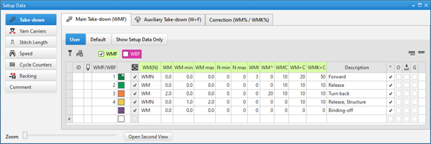
Column labels of the main take-down (WMF) tool window
|
Column |
Display | |
|---|---|---|
|
ID / IDv / ID^ |
Consecutive numbering and sorting of the entries | |
|
|
Selecting the main take-down value to enter it in the control column | |
|
WMF / WBF |
Index for indirect allocation of the fabric take-down value for the main take-down Multiflex or belt take-down | |
|
Color |
Display of colors to enter in the control columns | |
|
WM(N) |
WM |
Fabric take-down value when this is not changed in accordance with the quantity of needles. |
|
WMN |
Fabric take-down value when this is changed in accordance with the quantity of needles (fabric width). | |
|
WM |
Fabric take-down value when this is not changed in accordance with the quantity of needles. | |
|
WM min |
Fabric take-down value for minimum fabric width | |
|
WM max |
Fabric take-down value for maximum fabric width | |
|
N min |
Quantity of needles for minimum fabric width | |
|
N max |
Quantity of needles for maximum fabric width | |
|
WMI |
Fabric take-down impulse value | |
|
WM^ |
Specification of a number of degrees for the reverse rotation of the take-down | |
|
WMC |
Value for the sensitivity of the stop motion control of the main take-down | |
|
WM+C |
Specification of the system number for the fabric take-down control | |
|
WMK+C |
Specification of the system number for comb monitoring | |
|
Column |
Display | |
|---|---|---|
|
Description |
Comment on the use of the entry. | |
|
* |
|
Entry is not defined as favorite, meaning the entry is only within the Default table available. |
|
|
Entry is defined as favorite, meaning the entry is available within the User table or directly via the context menu of the control columns. | |
|
O |
|
Value cannot be overwritten (Overwrite) by a value of another table. |
|
|
Value can be overwritten (Overwrite) by a value of another table. (Default) | |
|
|
|
The entry will not be applied to the Setup data
|
|
|
The entry will be applied to the Setup data.
| |
|
G |
|
All settings of the Default or User
table are STOLL defaults (STOLL Template).
|
|
|
These settings of the Default or User
table are now User Standards (User-Template)
| |

Specify the favorites:
-
Design Pattern is selected.
- 1
- Open the Pattern Parameters tool window.
- 2
- Select the Take-down section.
- 3
- Select the Main Take-down (WMF) / Default tab.
- 4
- Mark the desired entry of the table in the * column as
 .
. - 5
- Close the tool window with .
- The selected entry will be displayed in the context menu and can be inserted in the design pattern for the main take-down.
Add a new entry in the main take-down (WMF) tab:
: New entries can only be added in the User
tab.
-
Design Pattern is selected.
- 1
- Open the Pattern Parameters tool window.
- 2
- Select the Take-down section.
- 3
- Select the Main Take-down (WMF) / User
tab.
- 4
- Set the cursor in the left table column to the row.
- 5
- Call up the Add Table Row context menu.
- A new entry will be added at the end of the table.
- 6
- Make the desired specifications in the columns of the new entry.
- 7
- Close the table with .
- Changes are saved to the table and are available in the project for each order and for all of its individual patterns.
: The changes will be saved to the *.spf file when saving the project.
Add entry of the Main take-down (WMF) tab to the pattern:
-
Design Pattern is selected.
- The Main Take-down (WMF) control column is displayed.
- 1
- Open the Pattern Parameters tool window.
- 2
- Select the Take-down section.
- 3
- Select the Main Take-down (WMF) / User
tab.
- 4
- Select the desired main take-down value in the column.
- 5
- Enter the selected main take-down value in the control column.
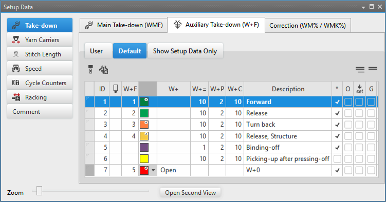
- Auxiliary Take-down (W+F)
Change specifications for the auxiliary take-down in the pattern:
: In the  control column the value W+F1 is entered by default and the value is set to 'Don't Care'. This allows for activating / deactivating the auxiliary take-down at the machine.
- You see and change the default settings for the auxiliary take-down in the Design Pattern.
- The control column is displayed.
- 1
- Open the existing Pattern Project and save it with a new name via the / menu.
- or -
Create new Pattern Project with an individual pattern. - 2
- In the document window Design Pattern, position the cursor on the control column and click the RMB.
- or -
Open the Auxiliary take-down context menu in the 2nd row of the table header containing the default settings with RMB. - The context menu for the auxiliary take-down (W+F) appears.
- The auxiliary take-down functions (W+F) used in the pattern are displayed and are marked by the symbol.
- The entries marked as favorites in the Auxiliary Take-down (W+F) / Default tab under the Take-down section of the Pattern Parameters
tool window are displayed.
- 3
- Select the desired auxiliary take-down value and enter it in the control column.
- or -
Fill a selection.
: The auxiliary take-down values (W+F) shown in the context menu correspond to the table in the Pattern Parameters
tool window under the Take-down section of the Auxiliary Take-down (W+F) / User
tab.
Select an entry of the Auxiliary Take-down (W+F) tool window and change it:
- Design Pattern document window is selected.
- The Auxiliary Take-down (W+F) control column is displayed.
- 1
- Open the selection list in the Home ribbon at Tool Windows and select Pattern Parameters
.
- or -
Directly under Parameter click thePattern Parameters
icon. - The Pattern Parameters
tool window appears.
- 2
- Select the Take-down section.
- 3
- Auxiliary Take-down (W+F) tab / Default
- or -
Select User . - 4
- Select the desired auxiliary take-down value in the
 column and enter it in the control column.
- The default setting will be overwritten in these design rows.
Options in the toolbar
| Selecting the default value to enter in the control column |
| Deleting an entry in the |
| Show Pattern-related Values |
| Hide Pattern-related Values |


Column labels of the auxiliary take-down (W+F) tool window
Column | Display |
|---|---|
ID | Consecutive numbering and sorting of the entries |
| Selecting the speed value to enter it in the control column |
W+F | Index for indirect allocation to the auxiliary take-down |
Color | Display of colors to enter in the control columns |
W+ | Open or close the auxiliary take-down |
W+= | Speed of auxiliary take-down |
W+P | Value for the contact pressure of the auxiliary take-down (CMS 822 only) |
W+C | Specification of the system number for the auxiliary take-down control |
Column | Display | |
|---|---|---|
Description | Comment on the use of the entry. | |
* |
| Entry is not defined as favorite, meaning the entry is only within the Default table available. |
| Entry is defined as favorite, meaning the entry is available within the User table or directly via the context menu of the control columns. | |
O |
| Value cannot be overwritten (Overwrite) by a value of another table. |
| Value can be overwritten (Overwrite) by a value of another table. (Default) | |
|
| The entry will not be applied to the Setup data
|
| The entry will be applied to the Setup data.
| |
G |
| All settings of the Default or User
table are STOLL defaults (STOLL Template).
|
| These settings of the Default or User
table are now User Standards (User-Template)
| |
 : All entries used in the pattern are applied by default to the Setup data.
Specify the favorites:
- Design Pattern is selected.
- 1
- Open the Pattern Parameters tool window.
- 2
- Select Take-down section -> Auxiliary Take-down (W+F) tab.
- 3
- Select the Default tab.
- 4
- Mark the desired entry in the * column .
- 5
- Close the tool window with
 .
.
- The selected entry will be displayed in the context menu and can be inserted in the design pattern for the speed.
Add a new entry in the auxiliary take-down (W+F) tab:
: New entries can only be added in the User
tab.
- Design Pattern document window is selected.
- 1
- Open the Pattern Parameters tool window.
- 2
- Select the Take-down section.
- 3
- Select the Auxiliary Take-down (W+F) / User
tab.
- 4
- Set the cursor in the left table column to the row.
- 5
- With the RMB open the context menu and select .
- A new entry will be added at the end of the table.
- 6
- Make the desired specifications in the columns of the new entry.
- 7
- Close the table with .
- Changes are saved to the table and are available in the project for each order and for all of its individual patterns.
: The changes will be saved to the *.spf file when saving the project.
Apply entry of the Auxiliary take-down (W+F) tab to the pattern:
- Design Pattern document window is selected.
- The control column is displayed.
- 1
- Open the Pattern Parameters tool window.
- 2
- Select the Take-down section.
- 3
- Select the Auxiliary Take-down (W+F) / User
tab.
- 4
- Select the desired auxiliary take-down value in the column.
- 5
- Enter the selected auxiliary take-down value in the control column.
-
Carriage Speed
:
Create new index for the carriage speed in the Setup table and enter it into the control column.
Change the specifications for the carriage speed in the pattern:
- See and modify the default settings for the stitch lengths in the Design Pattern.
- The
 Speed (MSEC) control column is displayed.
- 1
- Open the existing Pattern Project and save it with a new name via the File / Save As menu.
- or -
Create new Pattern Project with an individual pattern. - 2
- In the document window Design Pattern, position the cursor on the Speed (MSEC) control column and click the RMB.
- or -
In the 2nd row of the table header, open the context menu containing the default settings with RMB. - The context menu for the Speed (MSEC) appears.
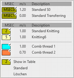
- The speed functions (MSEC) used in the pattern are displayed and are marked by the
 symbol.
 - The entries marked as favorites in the Pattern Parameters
tool window under the Speed section of the Default table are displayed.
- 3
- Select the desired main take-down value and enter it in the control column.
- or -
Fill a selection.
: The speed values (MSEC) displayed in the context menu correspond to the values of the Speed section in the User
tab of the Pattern Parameters
tool window
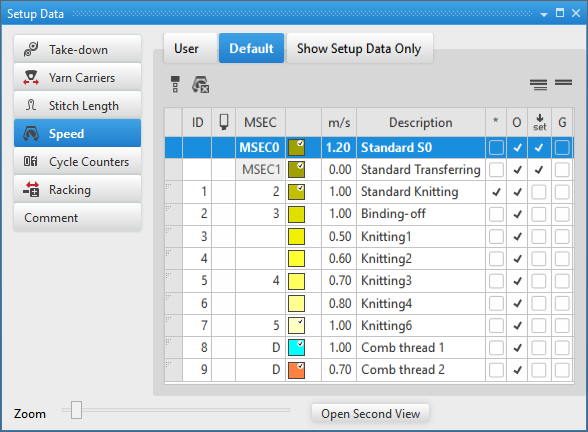
Select an entry of the Speed (MSEC) tool window and change it:
-
Design Pattern is selected.
- The Speed (MSEC) control column is displayed.
- 1
- Open the selection list in the Home ribbon at Tool Windows and select Pattern Parameters
.
- or -
click the Pattern Parameters
icon directly under Parameter. - The Pattern Parameters
tool window appears.
- 2
- Select the Speed (MSEC) section.
- 3
-
Default Tab
- or -
Select User . - 4
- Select the desired speed value in the column and enter it in the control column.
- The default setting will be overwritten in these design rows.
Options in the toolbar
|
|
Selecting the default value to enter in the control column |
|
|
Deleting an entry in the control column |
|
|
Show Pattern-related Values |
|
|
Hide Pattern-related Values |

Column labels of the Speed (MSEC) tool window
|
Column |
Display |
|---|---|
|
ID / IDv / ID^ |
Consecutive numbering and sorting of the entries |
|
|
Selecting the speed value to enter it in the control column |
|
MSEC |
Index for indirect allocation of the speed |
|
Color |
Display of colors to enter in the control columns |
|
m/s |
Value for the speed |
|
Column |
Display | |
|---|---|---|
|
Description |
Comment on the use of the entry. | |
|
* |
|
Entry is not defined as favorite, meaning the entry is only within the Default table available. |
|
|
Entry is defined as favorite, meaning the entry is available within the User table or directly via the context menu of the control columns. | |
|
O |
|
Value cannot be overwritten (Overwrite) by a value of another table. |
|
|
Value can be overwritten (Overwrite) by a value of another table. (Default) | |
|
|
|
The entry will not be applied to the Setup data
|
|
|
The entry will be applied to the Setup data.
| |
|
G |
|
All settings of the Default or User
table are STOLL defaults (STOLL Template).
|
|
|
These settings of the Default or User
table are now User Standards (User-Template)
| |
Specify the favorites:
-
Design Pattern is selected.
- 1
- Open the Pattern Parameters tool window.
- 2
- Select the Speed (MSEC) section.
- 3
- Select the Default tab.
- 4
- Mark the desired entry in the * column .
- 5
- Close the tool window with .
- The selected entry will be displayed in the context menu and can be inserted in the design pattern for the speed.
Add a new entry in the speed (MSEC) tab:
: New entries can only be added in the User
tab.
- Design Pattern document window is selected.
- 1
- Open the Pattern Parameters tool window.
- 2
- Select the Speed (MSEC) section.
- 3
- Select the User tab.
- 4
- Set the cursor in the left table column to the row.
- 5
- Call up the Add Table Row... context menu.
- A new entry will be added at the end of the table.
- 6
- Make the desired specifications in the columns of the new entry.
- 7
- Close the table with .
- Changes are saved to the table and are available in the project for each order and for all of its individual patterns.
: The changes will be saved to the *.spf file when saving the project.
Apply entry of the Speed (MSEC) tab to the pattern:
- The Design Pattern document window is selected.
- The Speed (MSEC) control column is displayed.
- 1
- Open the Pattern Parameters tool window.
- 2
- Select the Speed (MSEC) section.
- 3
- Select the User tab.
- 4
- Select the desired speed value in the column.
- 5
- Enter the selected speed value in the control column.
- 7
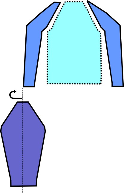
- Import the existing sleeve shape and position it.
: If the basic pattern is too small for the shape, then the size of the basic pattern will be automatically adjusted to the size of the shape.
Attention: Perhaps the color strap needs to be adapted.
- 8
- Open the line table by the
 Line Table button to get an explanation of a shape.
Structure of a basic shape
|
|
A |
Starting line |
|
B |
Area with shape modification because of widening | |
|
C |
Area without shape modification | |
|
D |
Area with shape modification because of narrowing | |
|
E |
End line | |
|
| ||
|
| ||

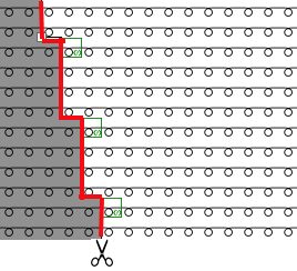
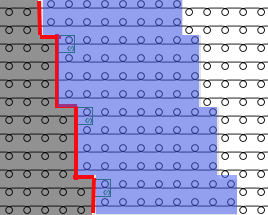
Fading-out
Exchange of the knitting mode at the shape edges
While cutting out the shape, the knitting mode is replaced at the shape edges.
|
|
1 |
Cutting-out the shape
|
|
|
2 |
Marked area (blue):
|
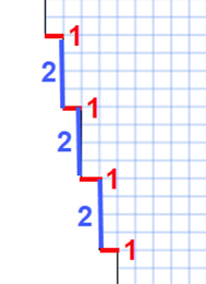
Widening
Widening of a fabric piece
|
|
1 |
Step width of widening
|
|
2 |
Step height of widening = Number of rows between two widening steps
| |
|
Widening Width |
Depending from the selected widening module
| |
Narrowing
Narrowing of a fabric piece
 : The transfer of stitches results in double stitches (fashioning marks).
|
|
1 |
Step Width
|
|
2 |
Step height = Number of rows between two narrowing steps
| |
|
Narrowing Width |
Depending on the knitting mode of the basic pattern | |
Rules for a raglan sleeve shape in the SJ knitting mode
|
Shape Attributes |
Rules |
|---|---|
|
Knitting Mode |
Single Jersey |
|
Step width of widening |
1 needle (stitch) per knitting row |
|
Step height of widening |
As desired |
|
Quantity of rows without shape modification |
As desired |
|
Step width when narrowing |
1 - 3 needles (stitches) |
|
Step height when narrowing |
As desired |
|
Narrowing Width |
As desired |
|
Fading-out Width |
As desired |
|
Knitting mode for fading-out |
Front Stitch with Transfer (default) |
- 9
- Click the
 Yarn Carriers button under Preview in the Home ribbon.
 - The document window is opened as view and the Yarn Carriers ribbon appears.
|
Yarn Carrier Color as Background | ||
|
|
Switching the view between the different pattern colors
| |
|
| ||
|
Show Knitting-out | ||
|
|
inactive |
Knitting-out of the yarn carriers is not displayed in the graphic. |
|
Active |
Knitting-out of the yarn carriers is displayed in the graphic.
| |

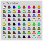
- 10
- Open the tool window with the Yarn Carriers button ->
 Show Yarn Carriers -> Available Yarns and Yarn Carriers tab
- 11
- Select the desired yarn carrier.
- 12
- Make the following changes:
- Combine yarn carriers from the pattern with the yarn carriers from the start.
- Combine Yarn Carriers
- Do Not Combine Yarn Carriers
- Allocate the yarn carriers to the rails.
- 13
- Apply the changes:
Edit group -> Apply
- or -
Edit group -> Apply and Close
|
|
Synchronize |
Applies the changes from the Design Pattern to the open Yarn Carrier View and synchronizes both views to the current state of the pattern. |
|
|
Apply |
Applies changes for yarn carriers to the Design Pattern. Other changes (e.g. of color parameters) will be applied at once. |
|
|
Apply and Close |
Applies changes for yarn carriers to the Design Pattern and closes the view. Other changes (e.g. of color parameters) will be applied at once. |
|
|
Cancel and Close |
Rejects modifications and closes the Yarn Carrier View. Close with Cancel and Close if you only opened the Yarn Carrier view for control. |

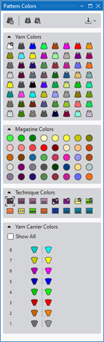
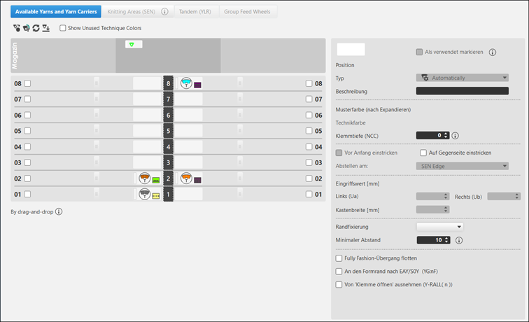
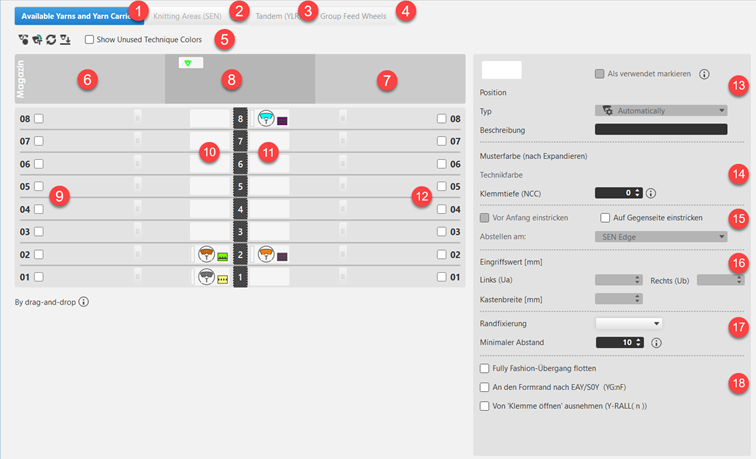
Explanation of the Yarn Carriers tool window:
|
| ||||||
|
1 |
Available Yarns and Yarn Carriers Tab | |||||
|
| ||||||
|
5 |
|
Returning yarn carriers to the magazine according to their position at the left or right side of the yarn carrier rails.
| ||||
|
|
Allocating the yarn carriers for technique colors to the yarn carrier rails according to the standard preallocation. | |||||
|
|
Returning yarn carriers from the yarn carrier rails to the magazine as 'undefined'.
| |||||
|
|
Allocating the yarn carriers from the magazine to the yarn carrier rails. | |||||
|
Show Unused Technique Colors | ||||||
|
|
In the view of the yarn carrier rails, only the technique colors used in the pattern are displayed. | |||||
|
|
In the view of the yarn carrier rails, the technique colors not used in the pattern are displayed as well. | |||||
|
6 |
Display of the yarn carriers for yarn and magazine colors regarding the positioning on the left side during rail allocation.
| |||||
|
7 |
Display of the yarn carriers for yarn and magazine colors regarding the positioning on the right side during rail allocation.
| |||||
|
8 |
Display of the yarn carriers for yarn and magazine colors undefined.
| |||||
|
9 / 10 |
|
Release for allocation of the rail with a yarn carrier left / right | ||||
|
|
No release for allocation of the rail with a yarn carrier left / right | |||||
|
10 / 11 |
Graphic presentation of the yarn carrier rails with the used yarn carrier types on the left / right side and specification of the corresponding colors. | |||||
|
| ||||||
|
Input panel for the selected yarn carrier | ||||||
|
13 |
|
Set as Used | ||||
|
|
Yarn carrier position is free for allocation | |||||
|
|
Yarn carrier position is not free for allocation
| |||||
|
Position |
Specification of the yarn carrier position of a yarn carrier color | |||||
|
Type |
| |||||
|
Description |
Comment on a yarn carrier
| |||||
|
14 |
Pattern Color (After Expanding) |
Display of the pattern color of the selected yarn carrier | ||||
|
Technique Color |
Display of the technique color of a selected technical yarn carrier | |||||
|
Clamping Depth |
Needle sinking of clamping and cutting needle | |||||
|
15 |
Knit-in before Start |
|
Selected yarn carrier is not knit-in in the Knitting-in before start function. | |||
|
|
Selected yarn carrier is knit-in in the Knitting-in before start function. | |||||
|
Knit-in to opposite side |
|
A yarn carrier remains on the corresponding side based on its home position. | ||||
|
|
A yarn carrier is knitted before the start to the opposite side of its home position.
| |||||
|
Stop at: |
| |||||
|
16 |
Engaging Value [mm] | |||||
|
At the Left (Ua) |
Engaging width for the left side | |||||
|
At the Right (Ub) |
Engaging width for the right side | |||||
|
Cabinet Width [mm] |
Specification depending on the yarn carrier type specified under Type
| |||||
|
17 |
Border Fixation |
Selection of the knitting mode for the border fixation (module) | ||||
|
Minimum Padding |
Distance for the border fixation in rows | |||||
|
18 |
Float Fully Fashion Transition |
|
At the end a yarn carrier is moved to the home position according to the setting in the Yarn Field Allocation. | |||
|
|
At the end a yarn carrier is moved to its home position without knitting.
| |||||
|
Go to Shape Edge after EAY/S0Y (YG:nF;) |
|
The yarn carrier will not be positioned at the counters #L and #R. | ||||
|
|
The yarn carrier will be positioned at the counters #L and #R and follows the shape. | |||||
|
Exclude from 'Open Clamp' (Y-RALL( n )) |
|
Selected yarn carrier is controlled by the Y-RALL function. | ||||
|
|
Selected yarn carrier will be excluded from the Y-RALL function and can be defined differently by the value (rows) at | |||||
|
| ||||||


 : Use:
 Color Parameters under
  .
.Additional tabs:
|
2 |
Knitting Areas (SEN) |
Working with several SEN areas:
|
|
3 |
Tandem (YLR) |
Change of the yarn carrier home position with tandem machines |
|
4 |
Group Feed Wheels |
Use when working with feed wheels
|

- 14
- Open the Expanded Symbol View with the
 Symbol button as preview if necessary to check the design pattern before further editing.
- and / or -
Open the expanded fabric view with the Fabric button
Expanded Symbol View
- The desired pattern is selected.
- 1
- Click the Preview button in the ribbon under Symbol.
: An additional document window appears with the expanded view of the design pattern.
- 2
- Close the document window with
 in the tab.
|
|
|
|---|---|
|
|
|
|
| |
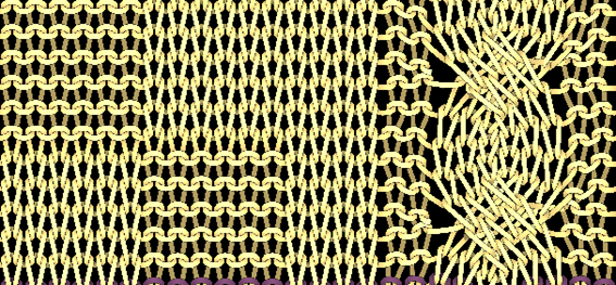
Expanded Fabric View
- The desired pattern is selected.
- 3
- Click the Preview button in the ribbon under Fabric.
: An additional document window appears with the fabric view of the design pattern.
- 4
- Close the document window by in the tab.
|
Fabric View | ||
|---|---|---|
|
| ||
|
Options in the status bar | ||
|
Expanded |
|
Show Expanded Fabric View with knitting rows and not knitting rows (transfer, cast-off, etc.) |
|
Collapsed |
|
Show Expanded Fabric View only with knitting rows |
|
Calculate Distortions |
|
Calculate the stitch distortion in order to get a realistic fabric view. |
|
Display in Relation of Stitch Density |
|
Show Expanded Fabric View with the specified stitch ratio |
|
Do Not Dissolve Drop Stitches |
|
Drop stitches are displayed. |
|
Show Protection Rows |
|
Display of the protection rows |
|
Draw the Draw Thread |
|
Display of the draw thread |
|
Yarn Texture |
|
View of the selected yarn texture from the Yarn Explorer |
|
Background |
|
Set background color for Expanded Fabric View |
|
| ||


- 15
-
 Start Technical Processing:
-
 Show symbol view after technical processing.
: Tip
Open the yarn carrier path in the "Technical View"  :
:
The yarn carrier for the protection thread 1 (#205) will be clamped after the start and at the end brought in again in the protection rows in the Float, Lock, Fabric selvedge module from Configuration.
Technical processing of an individual pattern:
- 1
- Select the desired pattern for the technical processing in the Patterns ribbon under Home .
- or –
Open the desired pattern in the Patterns tool window double clicking. - 2
- Start the technical processing for the selected pattern by the button in the Home ribbon under Technique.
: The result is shown in the document window by an unprotected symbol view.
- 3
- Close the document windows with in the tab of the document windows.: The data will not get lost and can at any time be shown and edited in a document window by the Symbol button.
- The success of technical processing is shown by in the Patterns tool window behind the pattern name.
|
| |
|
|
Technical Processing successfully performed |
|
|
Outdated technical processing
|

Presentation of the views
|
Design Pattern |
Processed Symbol View (not write-protected) |
|---|---|
|
|
|
|
Before Technical Processing: |
After Technical Processing:
|
|
| |

: Changes will be overwritten by re-processing .
Multiple Selection of Patterns for Technical Processing:
You can select several patterns for technical processing to start it more quickly.
- Several patterns are created.
- 1
- Click the
 Processing button in the Start ribbon under Multiple Processing
.
Processing button in the Start ribbon under Multiple Processing
. - The Technical Processing dialog box appears.
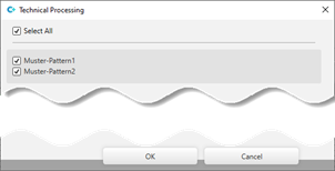
- 2
- Select the desired setting.
: You cannot start the technical processing for patterns greyed-out as data may be missing.
- 3
- Close the dialog box with OK.
- The technical processing is done automatically and shown by in the Patterns tool window.
- 4
- Close the document windows by in the tab of the document windows.: The data will not get lost and can at any time be shown and edited in a document window by the Symbol button.
- Successful processing is shown in the Patterns tool window by behind the pattern name.
- 16
- Generate
 Sintral.
Generate knitting program for a single pattern:
- Pattern is successfully processed.
- 1
- Select the desired pattern in order to create it for the knitting program in the Home ribbon under Patterns .
- or –
Open the desired pattern in the Patterns tool window double clicking. - 2
- Start the technical processing by the button in the Sintral ribbon.
- The *.sin; *.jac and *.setx files will be generated for the current patten.
The elements of the program are displayed by the following buttons:
|
|
Sintral |
Displaying the Sintral file |
|
|
Jacquards |
Displaying the packed Jacquard file |
|
|
MC Setup |
Displaying the Setup file |


Generate knitting programs for several patterns:
: You can select several patterns for the Generate Knitting Program procedure to start it more quickly.
- Several patterns or an order with several patterns is created and the technical processing is carried out for all patterns.
- 1
- Click the Generate Knitting Program button in the Start ribbon under Multiple Processing
.
- The Generate Knitting Program tool window is displayed.
- 2
- Select the desired setting.
- You cannot start the Generate Knitting Program processing for patterns greyed-out as data may be missing.
- 3
- Close the dialog box with OK.
- The processing step is automatically done for the selection and the patterns are marked with
 symbol in the Patterns tool window.
- 17
-
 Start Sintral Check
Sintral Check for a single pattern:
- The Generate Knitting Program processing step was performed so that the *.sin / *.jac / *.setx files are created for one pattern.
- 1
- Select the desired pattern for the Sintral Check in the Home ribbon under Patterns .
- or –
Open the desired pattern in the Patterns tool window double clicking. - 2
- Start the Sintral Check with the Sintral Check button.
- The Sintral Check dialog box appears.
- 3
- Start the simulation by the START button.
- The Simulation OK message appears
- 4
- Close the dialog box with X.
- 5
- Continue with the next pattern.
Run the Sintral Check for several patterns (multiple selection):
You can select several patterns for the processing step
Sintral Check, to start it more quickly.
- Several patterns or an order with several patterns is created and processing steps are carried out until Generate Knitting Program.
- 1
- Click the Sintral Check... button in the Start ribbon under Multiple Processing
.
- The Sintral Check tool window is displayed.
- 2
- Select the desired setting.
: You cannot start the Sintral Check for greyed-out patterns as data may be missing.
- 3
- Close the dialog box with OK.
- The processing step is automatically done for the selection and the patterns are marked with symbol in the Patterns tool window.
- 18
-
 Extract knitting program.
 - A program for the knitting machine will be created: CMS530.Pattern-1.zip.
Extract an individual pattern (*.zip) and save it:
- The Generate Knitting Program processing step was performed so that the *.sin / *.jac / *.setx files are created for one pattern.
- Sintral Check was done.
- 1
- Select the desired pattern in order to extract it in the Home ribbon under Patterns .
- or –
Open the desired pattern in the Patterns tool window double clicking. - 2
- Click the Extract button in the Start ribbon under Sintral.
- The Save As dialog box will appear.
- 3
- Change file name if desired.
- 4
- Select the desired path for the *.zip file.
- Local Drive
- USB Memory Stick
- Network Drive
- 5
- Close the dialog box with the Save button.
- After saving it, the zip file can be loaded and knitted on the machine.
Multiple selection of patterns or orders to create knitting programs:
You can select several patterns or orders for the processing step Extract..., to start it more quickly.
- Several patterns are created.
- The processing steps up to Generate Knitting Program, even up to Sintral Check... are done.
- 1
- Click the Extract button in the Start ribbon under Multiple Processing
.
- The Search Folder dialog box will be opened.
- 2
- Select an existing folder.
- or –
Create a new folder under the desired path by the Create folder button. - 3
- Select the folder.
- 4
- Close the dialog box with OK.
- Note appears: Following files successfully extracted:
- You cannot start the Extract... processing step for greyed-out patterns / orders as data may be missing.
- 5
- Close the dialog box with OK.
- The extracted knitting programs are available in the folder and can be loaded on the machine.
- 19
- Load knitting program into the machine.
: The extracted file CMS530.Pattern-1.zip can be loaded onto the machine with an USB stick or via Ethernet.