Step by Step to 'Pattern-11A'
- A pattern project with one pattern and the desired settings is created.
- 1
- Open the
 Modules tab.
 - 2
- Select Generate a new module via the context menu.
- The
 New Knitting Element dialog box will appear.
 - 3
- Make the following selection:
-
 Pattern Element
 - All Needles
- 4
- Close the dialog box with the OK button.
- The tool window appears with the corresponding template.
- 5
- Adjust the width and height of the template by deleting / inserting rows / columns:
- Example:
- Width: 30 needles
- Height: 2 rows
- 6
- Draw color areas with any desired yarn colors into the pattern element.
Example: Pattern Element with 3 Color Areas
- 7
- Create a Color Arrangement for the different structures based on the 3 color areas.
- 8
- Save and close the tool window of the knitting element.
- The created pattern element appears in the Pattern Element tab.
- 9
- To create a project-related lined shape, select the
 Shapes tab in the tool window.
- or -
Load an existing shape. - 10
- Select Create New Shape of Size M... in the context menu.
- The New Lined Shape tool window appears.
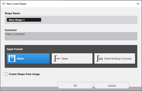
- 11
- Make the desired entries:
- Shape Name : Any
- Input Format : Stitch
- 12
- Confirm with the OK key.
- The new lined shape (basic shape) is graphically displayed in the Shapes tab and in a new document window
 as rectangle.
 : The default attributes will be used for the shape edges of the lined shape.
Menu File -> Options -> Lined Shape -> Options for New Lined Shape
- 13
- To create a lined shape based on the displayed rectangle in the ribbon Shape Editing under Properties, click the Line Table button.
- or -
Use the graphic displayed in the document window.
: The method (table or graphic) to create a project-related lined shape is freely eligible, since the views are always updated simultaneously.
- 14
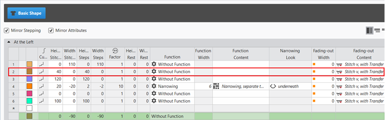
- Insert new shape lines in the table and enter the desired values for the basic shape.
- Standard attributes from configuration are assigned to those shape lines.
- 15
- Insert new shape lines in the table.
- 16
- Enter the desired values for the Neckline shape element.
- Standard attributes from configuration are assigned to those shape lines.
Example: Lined shape for Pattern-11A
|
Basic Shape: Front |
|
|
Rules for creating a shape for the knitting mode SJ:
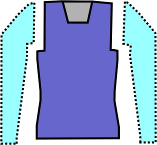
Example Front:
|
Shape Attributes |
Rules / possible settings |
|---|---|
|
Knitting Mode: |
Single Jersey |
|
Step width of widening |
1 needle (stitch) per knitting row |
|
Step height of widening |
As desired |
|
Quantity of rows without shape modification |
As desired |
|
Step width when narrowing |
1 - 3 needles (stitches) |
|
Step height when narrowing |
As desired |
|
Fading-out Width |
As desired |
|
Knitting mode for fading-out |
Front Stitch with Transfer |
|
Binding-off width: |
Stepping > 3 stitches |
|
Binding-off methods |
Binding-off, Structure, Single Jersey
|
- 17
- Allocate the desired attributes to the shape lines of the basic shape.
- 18
- Open the graphic of the basic shape in the xx document window.
- 19
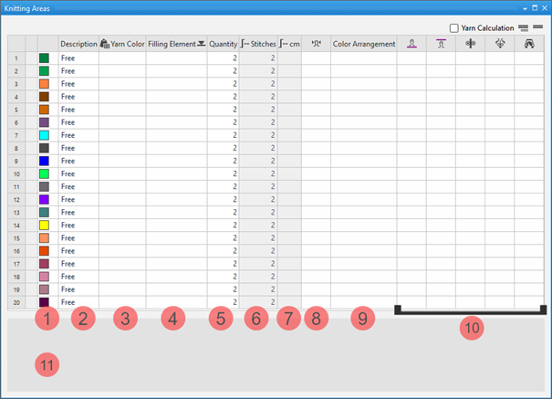
- Click the
 Knitting Ranges button under Parameter in the Shape Editing ribbon.
 - The Knitting Ranges tool window appears.
|
| ||
|
1 |
Colors |
Display color of the knitting range in the lined shape |
|
2 |
Description |
Definition of a knitting range |
|
3 |
|
Allocation of: |
|
4 |
Filling Element |
Selection of a knitting element / needle action / structure / pattern element to fill the knitting range |
|
5 |
Quantity |
Height of the knitting range by stitch rows |
|
6 |
|
Display of the total height by stitches |
|
7 |
|
Display of the total height by cm
|
|
8 |
|
Assignment of a stitch density from the stitch density tool window |
|
9 |
Color Arrangement |
Assignment of Color Arrangements |
|
10 |
|
Assignment of a stitch length for the front needle bed |
|
|
Assignation of a stitch length for the rear needle bed | |
|
|
Assignment of a take-down value | |
|
|
Assignment of a auxiliary take-down value | |
|
|
Assignment of a machine speed | |
|
11 |
List of the shapes (fabric pieces), where the selected knitting range is in use.
| |


 button.
- 20
- Create the desired knitting ranges in the Knitting Ranges tool window.
Example:
|
|
|
|
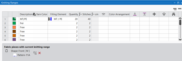
- 21
- Add the created knitting range to the shape point of the basic shape.
Enter the created knitting ranges into the shape and position it:
- Shape is created as lined shape.
- The knitting ranges are available in the Knitting Ranges tool window.
- Lined shape is opened in the xx document window.
- 1
- Select the desired shape point by the LMB to which you want to assign the knitting range.
- 2
- Open the context menu and select Assign Knitting Range.
- List of the knitting ranges appears to select one.
Multiple selection is possible. - 3
- Select the desired knitting range.
- The knitting range appears in the assigned color at the the shape line point of the lined shape.
|
|
Enable the view of the knitting ranges in the |
|
|
Disable the view of the knitting ranges in the |
|
|
Display of the knitting ranges in the |

- 4
- Position the inserted knitting range.
|
| ||
|
1 |
Selecting knitting ranges to replace the inserted knitting range. | |
|
2 |
Specify the Distance in Stitches in relation to the shape line point | |
|
3 |
Insert Knitting Range Downwards | |
|
|
Knitting range will be inserted above the shape line point | |
|
|
Knitting range will be inserted below the shape line point | |
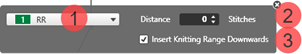


If you insert several knitting ranges, they may overlap each other.
You can specify the order of overlapping of the knitting ranges and with it, the motif in the pattern.
- Several knitting ranges are inserted into the shape.
- These knitting ranges are overlapping.
- 1
- Select the desired knitting range.
- 2
- Select the desired function under Arrange Objects in the Shape EditingShape Editing ribbon
- or -
In thexx document window, in the selected knitting area, select the Rearrangecontext menu with desired function.
|
|
Bring to Front |
The selected knitting area / shape element is positioned in the foreground (covering) in relation to all other knitting areas / shape elements. |
|
|
Send to Back |
The selected knitting area / shape element is positioned in the background (overlapped) in relation to all other knitting areas / shape elements. |
|
|
Bring Forward |
The selected knitting area / shape element is positioned one layer to the front. |
|
|
Send Backward |
The selected knitting area / shape element is positioned one layer to the back. |


- 22
- Minimize or close the Knitting Ranges tool window.
- 23
- In the Shapes tool window select the created shape with LMB.
- 24
- Open the context menu -> Position Shape -> select Pattern name.
- The shape is floating in the selected basic pattern.
- 25
- Row selection over the entire height of the inserted pattern element.
- 26
- Open the context menu and select Selection
/
 Create Color Arrangement:
.
Create Color Arrangement:
.
- or -
Click directly the button in the ribbon. - The Color Arrangement Editor appears displaying the 'Default knitting process for Intarsia' from the selected pattern rows.
- 27
- Modify the displayed 'Default knitting process for Intarsia' as desired.
Example:
- 28
- Check the correctness of changes by the
 Check button.
 - 29
- Close the Color Arrangement Editor.
- Color Arrangement is saved to the
 CA tool window.
 - 30
- Re-open the Knitting Ranges tool window if necessary.
- 31
- In the table -> Color Arrangement column, allocate the created Color Arrangement.
- The module color of the CA is entered and displayed in the Color Arrangement control column.
- 32
- If necessary to position the shape, change to the lined shape layer to move the shape in the document window with the
 button.
 - The knitting areas are linked to the shape, whereby this information is taken along with the positioning.
- 33
- Start the
 Technical
Processing.
Technical
Processing.
Show the symbol view after technical processing with the button.
 - 34
- Generate
 Sintral.
 - 35
- Start the
 Sintral Check.
 - 36
-
 Extract the knitting program.
 - A program for the knitting machine will be created: CMS530.Pattern11A.zip.
- 37
- Load knitting program into the machine.
 : The extracted file CMS530.Pattern-11A.zip can be loaded onto the machine with an USB stick or via Ethernet.