Step by Step to 'Pattern-10'
- A pattern project with one pattern and the desired settings is created.
- 1
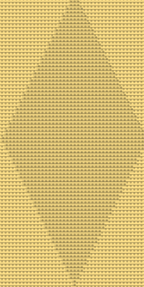
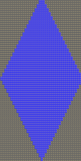
- Draw the desired SJ structure with:
-
 Maille avant avec report
-
 Maille arrière avec report
|
Presentation in plating color |
Presentation by module color |
|
|
|
- 2
- Select a structure in the width and height.
- 3
- Create pattern element from selection:
- With CTRL + C create a temporary pattern element to draw.
- Open the context menu -> Sélection
-> select
 Élément du dessin:
Pattern element is saved in the Parties de dessin tab.
- 4
- Draw-in the pattern element, with the help of the center of the pattern field, several times to the left and right into the basic pattern.
- 5
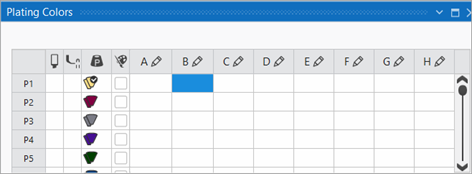
- With the
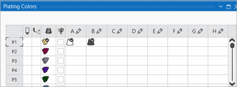
 button in the Couleurs de dessin tool window open the Couleurs de vanisage dialog box.
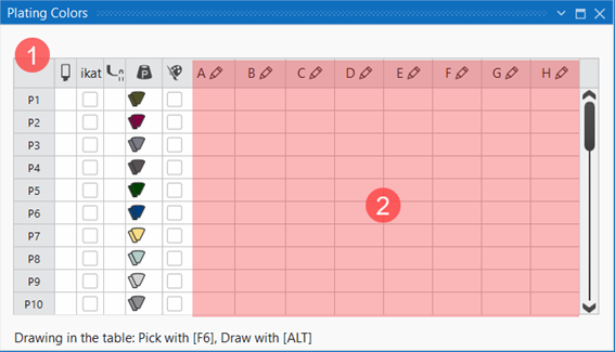
 - The Couleurs de vanisage tool window appears.
| ||||
1 | Column 1 | Default entries from P1 to P40 to use in the pattern for plating and knitting with weft yarn carriers
| ||
Column 2 |
| Selection of the plating color to draw in the design pattern | ||
Column 3 | ikat |
| Plating color is not defined as Stoll-ikat plating. | |
| Plating color is defined as Stoll-ikat plating. | |||
| ||||
Column 4 |
| Define presser foot type
| ||
Column 5 |
| Color value of the plating color
| ||
Column 6 |
|
| The color value of the plating color is not automatically mixed from the selected colors. | |
| The color value of the plating color is automatically mixed from the selected colors. | |||
| ||||
2 | Enter the different colors and settings for plating or knitting with weft yarn carriers in the columns A to H via the | |||


- 6
- Under P1 (plating color 1) in the columns A to H allocate the desired colors for plating.
- In the column under P1 the automatically generated plating color is displayed.
 : You can make up to 8 entries (columns A - H) for plating or for knitting with weft yarn carrier.
- 7
- If necessary change the color value in the column via the

 menu.
menu. - 8
- Select the P1 entry in the
 column.
 - 9
- Draw-in the plating color into the desired pattern rows, for example in the entire pattern height, of the design pattern.
- 10
- For plating the start, draw the plating color in the corresponding rows in the local 'Start' knitting element.
- A desired start is inserted in the design pattern.
- 1
- Position the cursor in the design pattern in the area of the 'Start'.
- 2
- Open the context menu with RMB.
- 3
- Select a Ouvrir le module....
- The tool window of the local knitting element with the knitting specifications of the selected start is displayed.
- 4
- Draw-in the P1 plating color in the knitting rows of the start.
- 5
- Close the tool window of the 'Start' knitting element.
- 6
- Enter changes with Accepter into the design pattern.
- The start is worked with the plating color P1.
- 11
- Close the tool window.
- 12
- To create a project-related lined shape, select the
 Coupes tab in the tool window.
 - 13
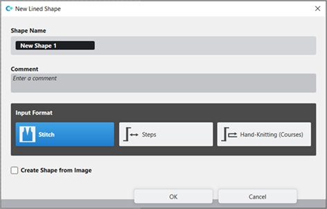
- Open the context menu with RMB and select Créer une nouvelle coupe dans la taille M... .
- The Nouvelle coupe de ligne tool window is opened.
| |||
Nom de la coupe | Name for the shape element | ||
Comment | Information about the shape | ||
| |||
Input Format | |||
Maille | Entry in the table of the lined shape
| ||
Escaliers | Entry in the table of the lined shape
| ||
Tricot main (tours) | Entry in the table of the lined shape
| ||
Rules for widening with hand knitting | |||
| Knitting before widening following the start | ||
| Widening before knitting following the start (default setting) | ||
Créer une coupe à partir d'une image |
| No images will be used | |
| Use image as template | ||


- 14
- Make the desired entries:
- Nom de la coupe : Any
- Format d'entrée : Stitch
- 15
- Confirm with the OK key.
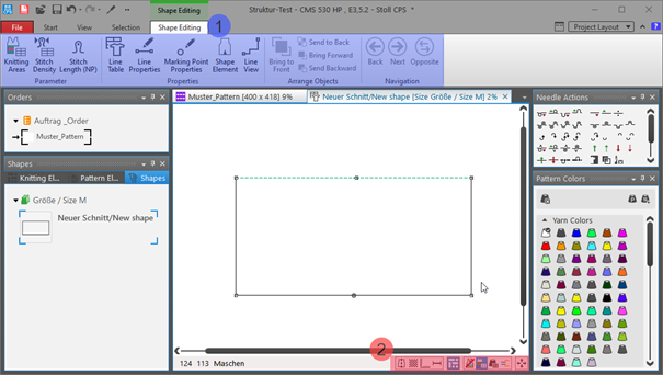
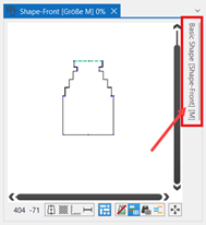
- The new lined shape (basic shape) is graphically displayed in the Coupes tab and in a new document window
 as rectangle.
: Default attributes are used for the shape edges of the lined shape.
Menu Fichier -> Options -> Coupe de ligne -> Options pour nouvelle coupe de ligne
Document window
| |||
1 | Élaboration de la coupe ribbon | ||
Group Paramètre | |||
| Zones de tricotage | Create new knitting areas and display existing knitting areas | |
| Densité des mailles | Create new stitch density and display existing stitch density | |
| Longueur de la maille (NP) | Display of the | |
| Group Caractéristiques | ||
| Yableau des lignes | Display of the line table for entering the shape data | |
| Propriétés des lignes | Display of the line properties (attributes) of a selected shape edge | |
| Propriétes du point de marquage | Display of the marking point properties (attributes) of a selected marking point | |
| Élément de coupe | Display of the shape element properties of a selected shape element
| |
| Vue de la ligne | Graphical display of a selected shape edge | |
2 | Status bar in the document window for shapes | ||
| Afficher l'axe de symétrie | ||
| Afficher le quadrillage des mailles | ||
| Afficher les axes du diagramme | ||
| Afficher les cotes de contrôle dans les mailles. | ||
| Afficher les icônes des points de marquage | ||
| Masquer les zones de tricotage | ||
| Afficher les zones de tricotage | ||
| Afficher les zones de tricotage (couleur de fil) | ||
| Afficher les zones de tricotage (couleur de CA) | ||
| Dépalcer l'objet sélectionné (point de coupe, point de marquage, zone de tricotage ou élément de coupe) avec les touches flèches du clavier (point de coupe uniquement au format d'insertion Mailles) | ||


- 16
- Open the docked line table by LMB in the document window.
- or -
Use the graphic displayed in the document window. - The table Coupe de ligne with the values of the rectangular shape appears.
: The method (table or graphic) to create a project-related lined shape is freely eligible, since the views are always updated simultaneously.
- 17
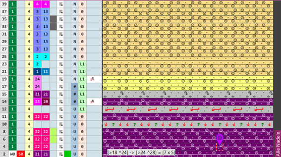
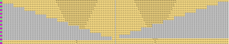
- Insert new shape lines in the table and enter the desired values for the basic shape.
Example: Lined shape for Pattern-10
|
Basic Shape: Front |
|
|
| ||||
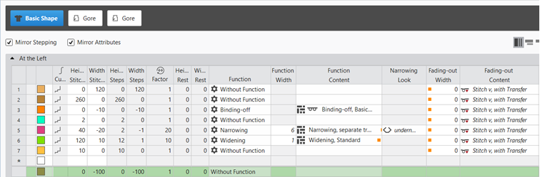
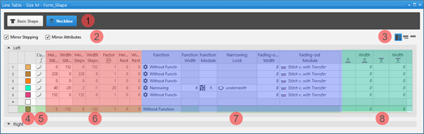
1 |
| |||
2 |
| Inverser les escaliers en miroir | Creating a symmetric shape of shape element
| |
| Faire une inversion miroir des attributs | Attribute changes carried out in the line table at the left and right. | ||
| Do not mirror attributes | Attribute changes are carried out in the line table at the left or at the right. | ||
| Do not mirror stepping | Creating an asymmetric shape / shape element
| ||
3 |
| Afficher toutes les propriétés | ||
| Afficher les sous-lignes | |||
| Masquer les sous-lignes | |||
4 | Display color for main lines and sublines of a selected line in the | |||
5 |
| Courbe |
| |
6 | Columns for entering the values for the lines of the lined shape in the input format
| |||
7 | Columns for the input of line attributes
| |||
8 | Specification for working with PTS (NPJ) for one line (shape edge)
| |||


 factor, height of rest and width of rest is calculated.
Insert shape line in a shape element:
: The shape lines are inserted symmetrically with both methods by default.
- In the Line Table:
Entry of a positive value: Widening and upwards
Entry of a negative value: Narrowing and down - Enter the desired values in the last table line with the * symbol. When confirming the input with the Enter key a new table line is inserted.
- Select a row -> open the context menu with RMB -> select Ajouter une ligne principale.
- Select a row -> open the context menu with RMB -> select Ajouter une ligne avant.
- or -
Select a Ajouter une ligne après.
: Only in the line table it is possible to create an asymmetrical line shape by deactivating  Inverser les escaliers en miroir.
- In the document window
- Position the cursor on a line of the displayed graphic -> open the context menu with RMB and select -> Insérer la ligne de coupe .
Changing line properties of a shape line
- Global project-related setting of the line properties via
 Configuration / Toutes les coupes tab
 - In the shape regarding a shape line
- In the Line Table
- In the document window
Changing Line Properties:
- In the Line Table
- Direct change of a line property in the corresponding column of the table
- Select a line in the table, open the tool window with the
 Propriétés des lignes button and make the desired entries.
 - In the document window
- Position the cursor on a line of the displayed graphic, select the context menu Propriétés des lignes and make the desired entries in the tool window.
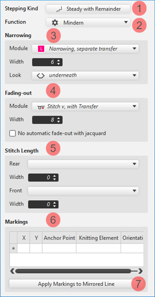
| 1 | Modification of the curve type | |
2 | Modification of the function of a shape line
| ||
3 | Modifications for the shape line with the Diminuer function | ||
4 | Modifications of the Masquer attribute for a shape line | ||
5 | Specification for a shape line for working with PTS in the shape edge | ||
6 | Display of the markings that are assigned to a shape line. | ||
Reprendre les marquages pour la ligne inversée | Applies the line-bound markings of the selected line to the line on the opposite.
| ||
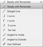
Changing curve type:
- In the Line Table
- In the
 Courbe column open the context menu with the RMB and select the desired curve type.
 - Select the line, open the Propriétés des lignes with the Propriétés des lignes button and select the desired curve type at Évolution des escaliers.
- In the document window
- Position the cursor on a line of the displayed graphic -> open the context menu with RMB and select -> Adapter l'évolution des escaliers....
- Select the desired Évolution des escaliers in the selection menu.
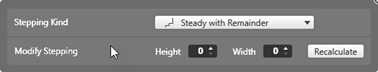
- When selecting the curve type
 homogène par rapport au reste via·Adapter les escaliers, specify the desired values for and of the steps.
 - : The window for entering specifications is displayed according to the selected curve type.
- Transfer the entry to the shape line with the Recalculer button.
- : The shape line is displayed in the graphic and in the line table as well.
- 18
- Allocate the desired attributes to the new shape lines:
- Function: Function content + Function width
- Fade-out: Fade-out content + Fade-out width
- Line 3:
- Function: Binding-off (at the external edge of the shape)
- Function content: desired bind-off method
Binding-off of the external edges of the shape |
The shape lines for binding-off at the external edge of the shape are at the same height in the line table.
|
: The shape is always even numbered in the total width (width of fabric piece).
- 19
- In this pattern example, an odd numbered fabric piece width is necessary due to the structure:
- In the Yableau des lignes, enter values for the left fabric piece and keep
 Inverser les escaliers en miroir enabled.
 - Set the basic shape to an odd width using Propriétés de la coupe.
- 20
-
Call up Propriétés de la coupe.
Position the cursor in the opened document window xx -> context menu with RMB -> select Propriétés de la coupe
- or -
select the shape in the Coupes tool window -> context menu with RMB -> select Propriétés de la coupe - 21
- Click on the
 Largeur impaire selection.
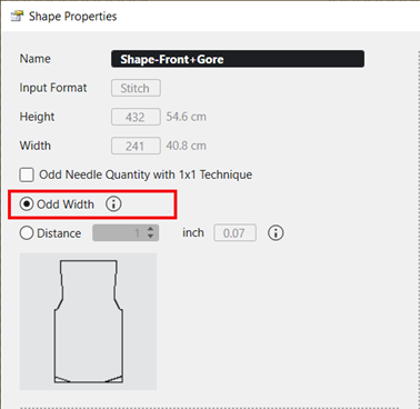
- The fabric piece width is widened by 1 needle.
: This setting also has an effect on the neckline shape element, i.e. the V-neck shape element starts with 1 needle.
- 22
- In the Yableau des lignes tool window, position the cursor in the area beside the
 coupe de base button, open the context menu with RMB and call-up Ajouter un nouvel élément de coupe....
- or -
Position the cursor in the document window (graphic), open the context menu with the RMB and select Ajouter un nouvel élément de coupe.... - 23
- Select Asymétrique in the
 Gousset selection menu.
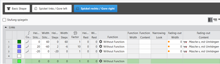
 - 24
- In the line table of the new shape element enter the desired values.
- The newly created shape element is displayed in the graphic and in the line table as well.
|
Shape Element Type: Gore asymmetrical |
|
|
|
|
- 25
- Select Gousset shape element.
- 26
- Open the context menu with RMB and select
 Retourner verticalement.
 - 27
- Then open the context menu again -> select Dupliquer en miroir.
- New knitting element is saved and is displayed in the basic shape.
- 28
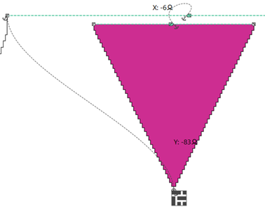
- To position a Gousset shape element, open the input window by double click and enter the coordinates.
- or –
Place the shape element at the desired position with the LMB pressed. - 29
- Make the positioning for both shape elements.
- 30
- If necessary, change the anchor (shortcut).
|
|
|
|
Positioning of a shape element in the basic shape
:
Every shape element gets a link (anchor) to a shape point in the basic shape during its creation.
Condition:
- A basic shape with a shape element is created.
- Position the cursor in the shape element.
- Reposition the shape element with the LMB pressed.
- or -
Move the shape with the arrow keys of the keyboard.
- or -
Open the coordinate display in the shape element double-clicking LMB and enter values. - : The anchor point becomes visible with its X and Y coordinates in the Encolure shape element.
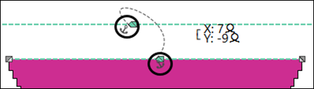
- Change the positioning if necessary.
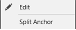
Possibilities for editing an anchor via the context menu
| |
| Tool window for manually changing the values of X and Y coordinates. |
Diviser l'ancre | Ungroup the grouped anchor in one anchor for X coordinate and one for Y coordinate, to be able to anchor one anchor with another shape element.
|

- 31
- In the Coupes tool window select the created shape with LMB.
- 32
- Open the context menu -> Positionner la coupe -> select Pattern name.
- The shape is floating in the selected basic pattern.
- 33
- Position the shape in the document window with the
 button.
 - 34
- Check shape lines, attributes and if desired make corrections.
- 35
- Click the
 Guide-fil button under Prévisualisation in the Accueil ribbon.
 - The document window is opened as view and the Guide-fil ribbon appears.
- 36
- Open the dialog box via
 Afficher le guide-fil.
 - 37
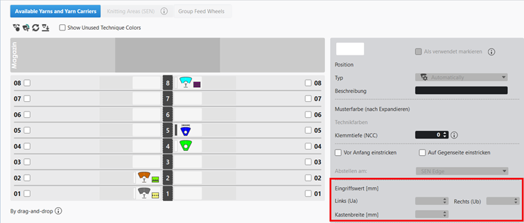
- Position the yarn carrier on the desired yarn carrier rails:
- Yarn carrier for yarn color #1 e.g. on rail 4
- Yarn carrier for yarn color #2 e.g. on rail 5
- 38
- Select and define yarn carrier:
- Yarn carrier on rail 4 as normal yarn carrier (leading yarn carrier)
- Yarn carrier on rail 5 as yarn carrier with 'Variable engaging width +/- (Ua-b)' (following yarn carrier)
- À gauche (Ua) : 21.5
- À droite (Ub) : 21.5
- 39
-
Start the
 Élaboration
technique:
Élaboration
technique: Show symbol view after technical processing.
 - 40
-
Generate
 Sintral.
 - 41
-
Start the
 Contrôle du Sintral.
 - 42
-
 Extraire the knitting program.
 - A program for the knitting machine will be created: CMS530.Pattern-10.zip.
- Load knitting program into the machine.
 : The extracted file CMS530.Pattern-10.zip can be loaded onto the machine with an USB stick or via Ethernet.