Step by Step to Pattern-3
- A pattern project with one pattern and the desired settings is created.
- 1
- Open
 Knit Explorer.
 - 2
- Then, in Knit Explorer under Módulos de estrutura -> Predefinição -> Petinet select the knitting element Petinet, Malha v to draw.
- 3
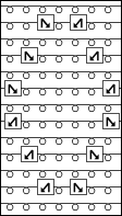
- Draw the desired structure.
|
Presentation in yarn color |
Presentation by module color |
|
|
|
- 4
- Select a structure in the desired width and height.
- 5
- Create from selection:
- With CTRL + C create a temporary pattern element to draw.
- Open the context menu -> Seleção
-> select
 Parte de amostra:
Pattern element is saved in the Partes de amostra tab.
- 6
- Draw-in the pattern element with the help of the center of the pattern field several times to the left and right into the basic pattern.
- 7
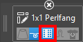
- Then, in Knit Explorer under Módulos de estrutura -> Predefinição -> Tipos básicos de tricotagem select the knitting element Perlé 1x1 to draw.
 : For working with PTS - different stitch length index in one technical row - the STOLL knitting elements Estrutura from the Knit Explorer already have different stitch lengths allocated. The stitch lengths are allocated in the control columns, as well as needle-exactly to the needle action.
- 8
- Activate
 Aplicar graduaçãoin the cursor attributes.
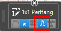
- 9
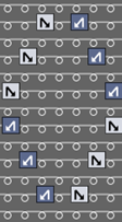
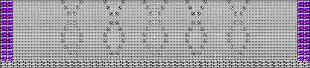
- Draw the Perlé 1x1 knitting element in the design pattern.
- The needle-exact stitch length from the knitting element will be entered in the design pattern.
|
Presentation of the design pattern in pattern color |
|
|
|
|
|
Presentation of the design pattern in stitch length (NPJ) |
|
|
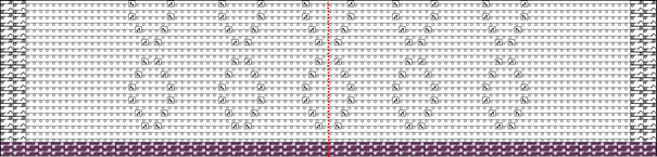
Result:
|
:
When positioning the knitting element Perlé 1x1 be sure that it is positioned correctly to Começo, 1x1.
This means that the structure 1x1 from the start without racking has to continue running in the structure of the 1x1 half cardigan.
Apply stitch lengths from knitting element to the control columns when drawing:
Condition:
The knitting element Perlé 1x1 has different stitch length entries in the control columns  and
and  as in the basic pattern.
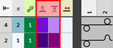
- Select a knitting element.
-
: The Cursor Attributes window with the currently available attributes appears.
- Via the
 Aceitar colunas de controle button make the desired setting to draw:
 - - Activated
Stitch lengths from the knitting element are entered in the control columns. - - Deactivated
Stitch lengths from the knitting element are not entered in the control columns. - Draw the knitting element in the design pattern.
-
: The stitch length is present in the control column and is therefore valid for the entire technical row. No Power Tension Setting (NPJ) is created.
Apply stitch lengths from knitting elements exactly to the needles when drawing into the design pattern:
Condition:
In the knitting element Perlé 1x1 there are entered different stitch lengths in the needle actions.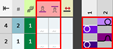
- Select a knitting element.
-
: The Cursor Attributes window with the currently available attributes appears.
- Via the Aplicar graduação button make the desired setting to draw:
- - Activated
Stitch lengths from the knitting element will be applied to the design pattern. - - Deactivated
Stitch lengths from the knitting element will not be applied to the design pattern. - Draw the knitting element in the design pattern.
-
: Now there are different stitch lengths available for PTS in a single technical row.
Draw stitch lengths from the table needle-exactly into the design pattern:
Condition:
- In the design pattern there are drawn different structures by areas.
- The standard stitch lengths are entered in the control columns and .
- In the status bar of the design pattern, switch from
 Cor da amostra to
  Graduação.
 - Open the selection list in the Início ribbon under Parâmetros at
 Janela de ferramentas
  and select the Graduação (NP) tool window.
 -
: The Graduação (NP) tool window appears.
- Select the Predefinição tab.
- Select the desired stitch lengths with the CTRL key in the
 and
and  columns additively.
 -
: The stitch length for the front and rear needle bed are at the cursor.
- Draw stitch lengths in the desired structure area needle-exactly into the design pattern.
-
: Now, different stitch lengths for PTS exist in one knitting row.
Result:
|
| |
|
1 |
Grey = no colored entry of a stitch length In these areas, the default stitch length from the control columns
|
|
2 |
Colored entry for further stitch lengths in one pattern row |

- 10
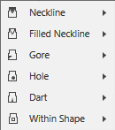
- To create a project-related lined shape, select the
 Cortes tab in the tool window.
 - 11
- Open the context menu with RMB and select Criar novo corte em tamanho M... .
- The Novo corte de linhas tool window is opened.
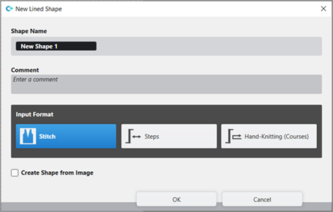
|
Input Format | ||
|
Malha |
Entry in the table of the lined shape
| |
|
Passos |
Entry in the table of the lined shape
| |
|
Tricotagem manual (voltas) |
Entry in the table of the lined shape
| |
|
Rules for widening with hand knitting | ||
|
|
Knitting before widening following the start | |
|
|
Widening before knitting following the start (default setting) | |
|
Criar corte da imagem |
|
No images will be used |
|
|
Use image as template | |
|
Comment |
Information about the shape | |


- 12
- Make the desired entries:
- Nome de corte : Any
- Formato de entrada : Stitch
- 13
- Confirm with the OK key.
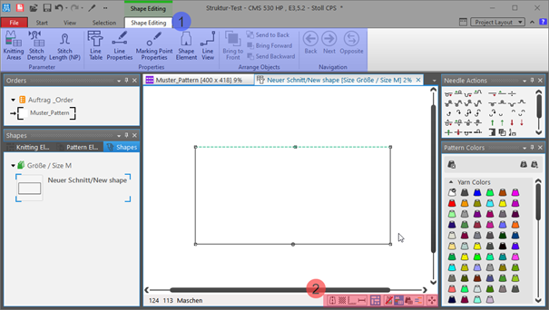
- The new lined shape (basic shape) is graphically displayed in the Cortes tab and in a new document window
 as rectangle.
: Default attributes are used for the shape edges of the lined shape.
Menu Arquivo -> Opções -> Corte de linhas -> Opções para o novo corte de linhas
Document window
|
| |||
|
1 |
Edição de corte ribbon | ||
|
Parâmetros Ribbon Group | |||
|
|
Áreas de tricotagem |
Create new knitting areas and display existing knitting areas | |
|
|
Densidade das malhas |
Create new stitch density and display existing stitch density | |
|
|
Graduação (NP) |
Display of the | |
|
|
Propriedades Ribbon Group | ||
|
|
Tabela de linhas |
Display of the line table for entering the shape data | |
|
|
Propriedades de linha |
Display of the line properties (attributes) of a selected shape edge | |
|
|
Propriedades de ponto de marcação |
Display of the marking point properties (attributes) of a selected marking point | |
|
|
Elemento de corte |
Display of the shape element properties of a selected shape element
| |
|
|
Vista de linhas |
Graphical display of a selected shape edge | |
|
2 |
Status bar in the document window for shapes | ||
|
|
Exibir eixo de simetria | ||
|
|
Exibir grelha de malhas | ||
|
|
Exibir eixos de diagrama | ||
|
|
Exibir dimensionamentos de controle | ||
|
|
Exibir os símbolos dos pontos de marcação | ||
|
|
Ocultar áreas de tricotagem | ||
|
|
Exibir áreas de tricotagem | ||
|
|
Exibir áreas de tricotagem (cor de fio) | ||
|
|
Exibir áreas de tricotagem (cor de CA) | ||
|
|
Deslocar o objecto selecionado (ponto de corte, marcação de ponto, área de tricotagem ou elemento de corte) com teclas de seta do teclado (ponto de corte só em formato de entrada Malhas) | ||


- 14
- To create a lined shape based on the displayed rectangle in the ribbon Edição de corte under Propriedades, click the Tabela de linhas button.
- or -
Use the graphic displayed in the document window.
: The method (table or graphic) to create a project-related lined shape is freely eligible, since the views are always updated simultaneously.
- 15
- Open Tabela de linhas in the ribbon.
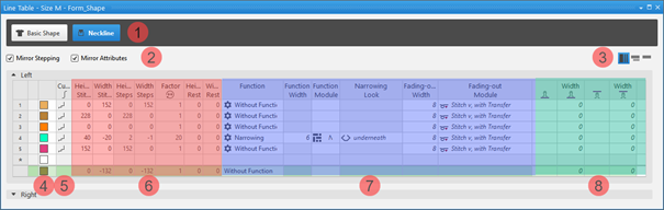
- The table Corte de linhas with the values of the rectangular shape is displayed.
- 16
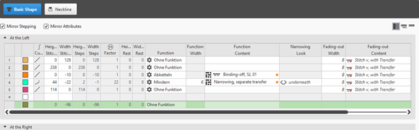
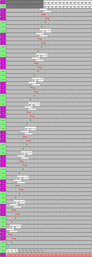
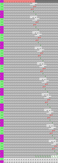
- Insert new shape lines in the table and enter the desired values for the basic shape.
Example: Lined shape for Pattern-3
|
Basic Shape: Front |
|
|
|
| ||||
|
1 |
| |||
|
2 |
|
Inverter escalonamento |
Creating a symmetric shape of shape element
| |
|
|
Inverter atributos |
Attribute changes carried out in the line table at the left and right. | ||
|
|
Do not mirror attributes |
Attribute changes are carried out in the line table at the left or at the right. | ||
|
|
Do not mirror stepping |
Creating an asymmetric shape / shape element
| ||
|
3 |
|
Exibir todas as propriedades | ||
|
|
Exibir linhas secundárias | |||
|
|
Ocultar linhas secundárias | |||
|
4 |
Display color for main lines and sublines of a selected line in the | |||
|
5 |
|
Curva |
| |
|
6 |
Columns for entering the values for the lines of the lined shape in the input format
| |||
|
7 |
Columns for the input of line attributes
| |||
|
8 |
Specification for working with PTS (NPJ) for one line (shape edge)
| |||


 factor, height of rest and width of rest is calculated.
Insert shape line in a shape element:
: The shape lines are inserted symmetrically with both methods by default.
-
In the Line Table:
Entry of a positive value: Widening and upwards
Entry of a negative value: Narrowing and down - Enter the desired values in the last table line with the * symbol. When confirming the input with the Enter key a new table line is inserted.
- Select a row -> open the context menu with RMB -> select Adicionar linha principal.
- Select a row -> open the context menu with RMB -> select Adicionar linha em frente.
- or -
Select Adicionar linha depois.
: Only in the line table it is possible to create an asymmetrical line shape by deactivating  Inverter escalonamento.
- In the document window
- Position the cursor on a line of the displayed graphic -> open the context menu with RMB and select -> Inserir linha de corte .
Changing line properties of a shape line
- Global project-related setting of the line properties via
 Configuração / Todos os cortes tab
 - In the shape regarding a shape line
Changing Line Properties:
- In the Line Table
- Direct change of a line property in the corresponding column of the table
- Select a line in the table, open the tool window with the
 Propriedades de linha button and make the desired entries.
 - In the document window
- Position the cursor on a line of the displayed graphic, select the context menu Propriedades de linha and make the desired entries in the tool window.
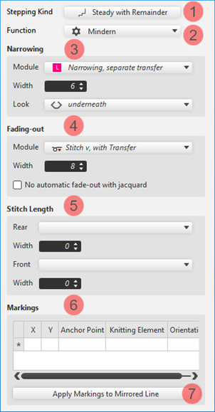
|
|
1 |
Modification of the curve type | |
|
2 |
Modification of the function of a shape line
| ||
|
3 |
Modifications for the shape line with the Minguar function | ||
|
4 |
Modifications of the Ocultar attribute for a shape line | ||
|
5 |
Specification for a shape line for working with PTS in the shape edge | ||
|
6 |
Display of the markings that are assigned to a shape line. | ||
|
Aplicar marcações à linha invertida |
Applies the line-bound markings of the selected line to the line on the opposite.
| ||
Changing curve type:
- In the Line Table
- In the
 Curva column open the context menu with the RMB and select the desired curve type.
 - Select line -> with the Propriedades de linha button open the Propriedades de linha and select the desired curve type at Seqüência de escalonamentos
- In the document window
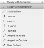
- Position the cursor on a line of the displayed graphic -> open the context menu with RMB and select -> Ajustar seqüência de escalonamentos....
- Select the desired Seqüência de escalonamentos in the selection menu.
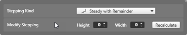
- When selecting the curve type
 uniformemente com resto via·Ajustar escalonamento, specify the desired values for and of the steps.
 -
: The window for entering specifications is displayed according to the selected curve type.
- Transfer the entry to the shape line with the Recalcular button.
-
: The shape line is displayed in the graphic and in the line table as well.
- 17
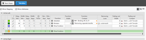
- Allocate the desired attributes to the new shape lines:
- Function: Function content + Function width
- Fade-out: Fade-out content + Fade-out width
- Line 3:
- Function: Binding-off (at the external edge of the shape)
- Function content: desired bind-off method
|
Binding-off of the left external edge of the shape |
Binding-off of the right external edge of the shape |
|
| |
|
|
|
|
|
|
: The knitting sequence when binding-off depends on the carriage stroke!
The height (number of knitting rows) until binding-off is as desired, since the binding-off edges are moved in height by the technical processing according to the carriage direction.
- 18
- In the line table, position the cursor in the area next to the
 Corte base button -> open the context menu by RMB -> select Adicionar novo elemento de corte....
 - 19
- In the selection menu select the desired shape element Decote -> symmetrically.
- 20
- Create the shape lines of the new shape element the same way as the basic shape.
- The newly created shape element is displayed in the graphic and in the line table as well.
|
Shape Element Type: Neckline symmetric |
|
|
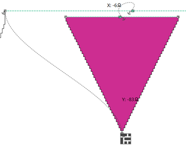
Positioning of a shape element in the basic shape
:
Every shape element gets a link (anchor) to a shape point in the basic shape during its creation.
Condition:
- A basic shape with a shape element Decote is created.
- Position the cursor in the shape element.
- Reposition the shape element with the LMB pressed.
- or -
Move the shape with the arrow keys of the keyboard.
- or -
Open the coordinate display in the shape element double-clicking LMB and enter values. -
: The anchor point becomes visible with its X and Y coordinates in the Decote shape element.
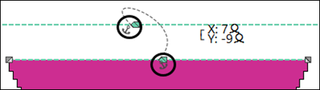
- Change the positioning if necessary.
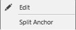
Possibilities for editing an anchor via the context menu
|
| |
|
|
Tool window for manually changing the values of X and Y coordinates. |
|
Distribuir âncora |
Ungroup the grouped anchor in one anchor for X coordinate and one for Y coordinate, to be able to anchor one anchor with another shape element.
|

- 21
- Allocate the desired attributes to the new shape lines:
- Function: Function content + Function width
- Fade-out: Fade-out content + Fade-out width
- Line 1:
- Function: Binding-off (at the neckline start)
- Function content: desired bind-off method
Variants of necklines
- Neckline start with only one needle (shape odd-numbered in the total width)
- Neckline start with 2 needles (shape even numbered in the total width)
- Neckline start with more than 2 needles -> Binding-off at the start
: Knitting element Start decote em V, cruzamento is linked with the marking point of the shape element Neck.
|
Graphic presentation of the neckline start |
|
|
|
|
|
| |
|
|
|
|
| |
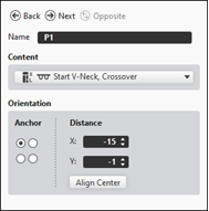

Adjusting the position of the Start V-Neck Crossover knitting element:
: Attention:
If a knitting element Start decote em V, cruzamento is connected to a shape line, then the knitting element at marking should be removed.
- In the Line Table
- Select a line in the table.
Open the tool window with the Propriedades de linha button and make the desired entries. - In the document window
- Position the cursor on a line of the displayed graphic and open the context menu.
Select Propriedades de linha and make the desired entries in the tool window.
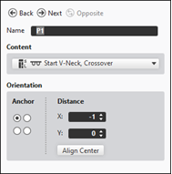
- Select the desired shape line.
- Open the tool window via Propriedades de linha.
- Make the following settings in the Marcações section:
- - X / Y: the positioning of the selected knitting element
- - Anchor Point: at which point of the shape line (start/end) should the knitting element be added
- - Knitting Element: specify desired knitting element
- - Orientation: specify desired point in the knitting element (reference point) for the positioning
- Make further changes if necessary.
-
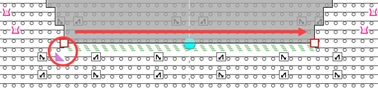
: The knitting element should be placed at the left shape line (endpoint), as the binding-off is done from left to right.
|
| |
|
1 |
Positioning of the Start decote em V, cruzamento knitting element with
|
|
2 |
Positioning of the Start decote em V, cruzamento knitting element with
|
|
3 |
Positioning of the Start decote em V, cruzamento knitting element with
|
: The knitting sequence when binding-off always depends on the carriage stroke!
|
|
Binding-off in the carriage stroke to the right >>
|
|
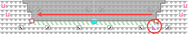
|
Binding-off in the carriage stroke to the left <<
|
|
|
Split the bind-off in the center
|
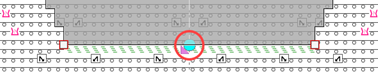
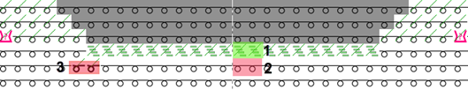
Draw-in the separation manually in the Finishing Layer:
- Shape is positioned in the design pattern.
-
 Símbolos de forma is enabled in the view of the design pattern.
- 1
- Via the layer user control, switch from
 Editar camada de amostra
to
Editar camada de amostra
to  Editar a camada de Finishing.
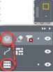
- 2
- In the tool window Ações da agulha -> Símbolos de forma -> select symbol
 Separação.
 - 3
- Insert manually in the Finishing layer the symbol Separação over 2 knitting rows.
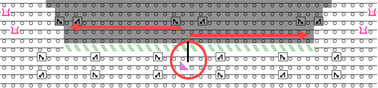
- 4
- Position starting module of the neckline start related to the symbol .
-
: The starting row of the neckline will be bound-off from the center.
- 22
- In the tool window Shapes select the created shape with LMB.
- 23
- Open the context menu -> Posicionar corte -> select Pattern name.
- The shape is floating in the basic pattern.
- 24
- Enable the
 button of the document window.
 - 25
- Position the shape on the basic pattern via
 .
. - 26
- Check shape lines, attributes and if desired make corrections.
- 27
- If necessary, allocate a sub-color to the left side of the neckline to add other attributes via the Parâmetros de cor table.
- 28
- Start the
 Processamento
técnico:
Processamento
técnico: Show symbol view after technical processing.
 - 29
- Generate
 Sintral.
 - 30
- Start the
 Controle Sintral.
 - 31
-
 Extrair the knitting program.
 - A program for the knitting machine will be created: CMS530.Pattern-3.zip.
- Load knitting program into the machine.
 : The extracted file "CMS530.Pattern-3.zip" can be loaded onto the machine with an USB stick or via Ethernet.