For advanced users: Private structure module for the V-neck start
- New Knitting Element
- Storage in
 Knit Explorer
 - New Local Knitting Element
- Storage in the opened pattern project
Create new knitting element:
- 1
- Click on the
 CREATE PLUS icon at the start of Yeni örme elemanı.
- or -
Click Yeni örme elemanı icon in the Knit Explorer.
- or -
Select Yeni modül... in the context menu of the Modüller tab.
 - 2
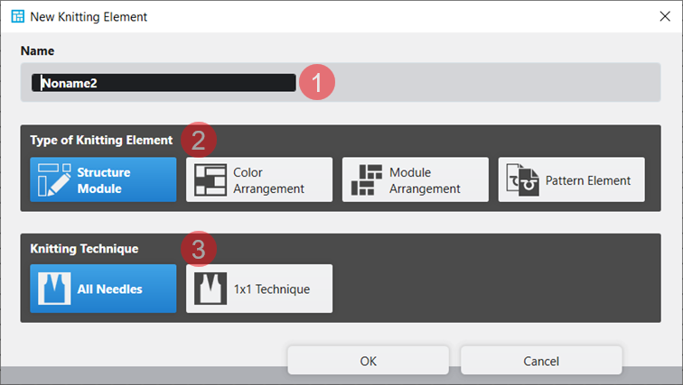
- The Yeni örme elemanı dialog box will appear.
|
| ||
|
1 |
Ad |
Enter the name of the new knitting element. |
|
2 |
Örme elemanı tipi |
Selection of the template for the new knitting element
|
|
3 |
Örme tekniği |
Selection of the basic knitting mode for the new knitting element
|
- 3
- Make the desired settings.
- 4
- Close the dialog box with the Tamam button.
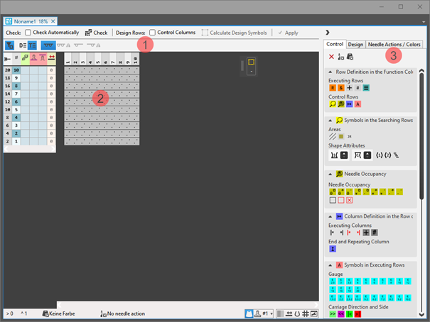
- The tool window appears with the corresponding template.
|
|
|
1 |
Kontrol et |
|
Otomatik |
The created knitting element are not automatically checked regarding the correct structure. |
|
|
Otomatik |
An automatic check is executed regarding the correct structure of the created knitting element. | ||
|
|
Kontrol et |
Checking of the created knitting element regarding the correct structure. | ||
|
Tasarım sıraları |
|
Kumanda sütunları |
Not applying the control column data from the technical rows to the design rows | |
|
|
Kumanda sütunları |
Applying the control column data from the technical rows to the design rows | ||
|
| ||||
|
|
Seçim |
Get the design symbols for the technical rows in the selected area created. | ||
|
|
| |||
|
|
| |||
|
|
| |||
|
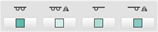
Presentation of symbols: |
| |||
|
|
|
Display of the drawing canvas for knitting with all needles. | ||
|
|
Display of the drawing canvas for knitting with all needles mirrored.
| |||
|
|
Display of the drawing canvas for knitting in 1x1 technique.
| |||
|
|
Display of the drawing canvas for knitting in 1x1 technique mirrored.
| |||
|
2 |
Display of the corresponding template with control columns and drawing canvas | |||
|
3 |
Kumanda |
Tab with all attributes for creating the different knitting element types | ||
|
Tasarım |
Tab with icons for changing / creating design rows | |||
|
İğne hareketleri / renkler |
Tab with needle actions and the pattern colors | |||


- 5
- Adjust the template width and height by deleting / inserting of rows / columns.
- 6
- Select the İğne hareketleri / renkler tab.
- 7
- Select the display of
 Teknik sıralar.
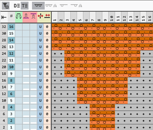
 - 8
- Draw the structure into the technical rows of the new knitting element with needle actions and without pattern color.
-or-
With needle actions and the desired pattern color draw the structure.
- The design rows are generated automatically.
|
Structure without pattern color |
Structure with stitch lengths | |
|
|
| |
|
1 |
Symbol |
In the design pattern in the presentation |
|
2 |
Needle Actions
| |
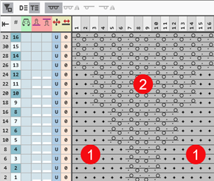

 display stitch length, draw-in the stitch lengths for the front and rear.
- 9
- If desired, define further control column data in the technical rows.
- 10
- Apply this control column data to the design rows with the
 Kumanda sütunları button activated.
 - 11
- Check the knitting element regarding the correct structure with the
 Kontrol et button.
 - 12
- Save and close the knitting element.
Create a new, local knitting element:
- A
 project is created and opened.
- 13
- In the tool window Modüller select the tab
 Modüller.
 - 14
- Call-up the Yeni modül... context menu of the tool window.
- The Yeni örme elemanı dialog box appears.
- 15
- Select the desired template.
- 16
- Select the knitting technique for the selected template.
- 17
- Confirm entries with Tamam.
- Tool window with template is opened.
|
|
|
1 |
Check |
|
Otomatik |
The created knitting element are not automatically checked regarding the correct structure. |
|
|
Otomatik |
An automatic check is executed regarding the correct structure of the created knitting element. | ||
|
|
Kontrol et |
Checking of the created knitting element regarding the correct structure. | ||
|
Design Rows |
|
Kumanda sütunları |
Not applying the control column data from the technical rows to the design rows | |
|
|
Kumanda sütunları |
Applying the control column data from the technical rows to the design rows | ||
|
| ||||
|
|
Seçim |
Get the design symbols for the technical rows in the selected area created. | ||
|
|
| |||
|
|
| |||
|
|
| |||
|
Presentation of symbols |
| |||
|
|
|
Display of the drawing canvas for knitting with all needles. | ||
|
|
Display of the drawing canvas for knitting with all needles mirrored.
| |||
|
|
Display of the drawing canvas for knitting in 1x1 technique.
| |||
|
|
Display of the drawing canvas for knitting in 1x1 technique mirrored.
| |||
|
2 |
Display of the corresponding template with control columns and drawing canvas | |||
|
3 |
Kumanda |
Tab with all attributes for creating the different knitting element types | ||
|
Tasarım |
Tab with icons for changing / creating design rows | |||
|
İğne hareketleri / renkler |
Tab with needle actions and the pattern colors | |||
- 18
- Adjust the template width and height by deleting / inserting of rows / columns.
- 19
- Select the İğne hareketleri / renkler tab.
- 20
- Select the display of Teknik sıralar.
- 21
- Draw the structure into the technical rows of the new knitting element with needle actions and without pattern color.
-or-
With needle actions and the desired pattern color draw the structure.
- The design rows are generated automatically.
|
Structure without pattern color |
Structure with stitch lengths | |
|
|
| |
|
1 |
Symbol |
In the design pattern in the presentation |
|
2 |
Needle Actions
| |
- 22
- If desired, define further control column data in the technical rows.
- 23
- Apply this control column data to the design rows with the Kumanda sütunları button activated.
- 24
- Check the knitting element regarding the correct structure with the Kontrol et button.
- 25
- Close the tool window with X.
- A new local knitting element is saved in the Modüller tab.
Properties of Knitting Elements
The properties define the behavior, the appearance and the size of a knitting element.
Özellikler Dialog Box:
- 26
- Select module.
- 27
- Open the context menu.
- 28
- Select
 Özellikler.
 - The Özellikler dialog box will appear.
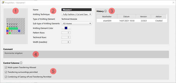
Example of a Technical Module:
|
| ||||
|
1 |
Graphic presentation of the selected type of knitting element | |||
|
2 |
Ad |
Name of the knitting element | ||
|
Örme tekniği |
Definition of the knitting technique for the use within the pattern | |||
|
Örme elemanı tipi |
Display of the selected type of knitting element
| |||
|
Örme elemanı alt tipi |
Selection of sub-types according to the selected knitting element type
| |||
|
Örme elemanı rengi |
Definition of a color for the display of the knitting element in the | |||
|
|
Display color for the different knitting elements or modules | |||
|
|
Display color for structure modules with the different knitting techniques | |||
|
Desen sıraları |
Quantity of pattern rows in the knitting element | |||
|
Teknik sırası |
Quantity of technical rows in the knitting element | |||
|
Genişlik [iğneler] |
Quantity of needles within one row of the knitting element | |||
|
3 |
Geçmiş |
Display of state of editing from creation until the last modification:
| ||
|
4 |
Yorum |
Entry of a comment or a description | ||
|
5 |
Kumanda sütunları |
Control Column Options
| ||
|
|
Options not allowed suppress the corresponding function in the control columns within the area of this knitting element. | |||
|
|
Allowed options enable the corresponding function in the control columns within the area of the knitting element. | |||


- 29
- Set the desired properties.
- 30
- Close the dialog box with
 .
.
- The properties are applied when using it in the pattern.
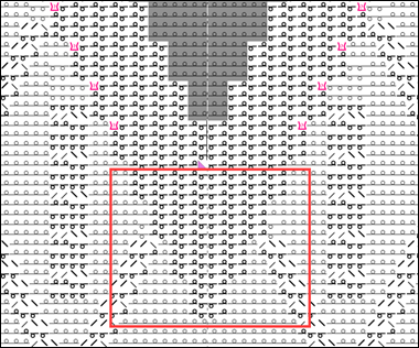
- Shape is positioned in the design pattern.
- 31
- Switch document window
 xxx with positioned shape via the layer user control to
  Çizgi kesimi düzeyini düzenle (Y)
.
Çizgi kesimi düzeyini düzenle (Y)
. - 32
- Position the cursor in this view where the marking point should be positioned.
- 33
- Open the context menu -> select
 İşaretleme noktası ekle.
 - The green marking point is inserted at this position.
- 34
- Position cursor on the point.
- 35
- Open the context menu with RMB -> select
 Özellikler.
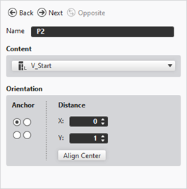
 - The tool window Marking Point Properties is opened.
- 36
- Make the following settings:
- Name: Name for the shape marking point
- Content: Allocate created knitting element from Knit Explorer or from tab Modüller (local knitting element)
- Orientation:
- Anchor: Selection of the reference point (hotspot) in the knitting element
- Distance: Positioning regarding the anchor
- 37
- Close the tool window.
Possibilities of storage of private knitting elements:
- In the Knit Explorer
 : Knitting element available for all projects
 - In the Desen projesi : Local knitting element related to the project
- The knitting element can be saved.
-
Dosya -> Farklı Kaydet : The knitting element is saved in any directory on the PC as xx.smf file.