Create New Knitting Element of the 'Structure Module' Type
The options to save a knitting element:
- In the
 Knit Explorer
 : Knitting element available for all pattern projects
 - In the
 Pattern Project: Local knitting element related to the project
 - The knitting element can be saved in a directory.
-
File -> Save As : The knitting element is saved in any directory on the PC as xx.smf file.
Create a new knitting element for structure in the Knit Explorer:
- 1
- Click on the
 New Knitting Element icon at the start of CREATE PLUS.
- or -
With the CREATE PLUS running, open the Knit Explorer and click the New Knitting Element icon. - The New Knitting Element dialog box appears.

|
1 |
Name |
Enter the name of the new knitting element. |
|
2 |
Type of Knitting Element |
Selection of the template for the new knitting element
|
|
3 |
Knitting Technique |
Selection of the basic knitting mode for the new knitting element
|
- 2
- Make the desired settings.
- 3
- Close the dialog box with the OK button.
- The tool window appears with the corresponding template.

|
1 |
Check |
|
Automatically |
The created knitting element are not automatically checked regarding the correct structure. |
|
|
Automatically |
An automatic check is executed regarding the correct structure of the created knitting element. | ||
|
|
Check |
Checking of the created knitting element regarding the correct structure. | ||
|
Design Rows |
|
Control Columns |
Not applying the control column data from the technical rows to the design rows | |
|
|
Control Columns |
Applying the control column data from the technical rows to the design rows | ||
|
| ||||
|
|
Selection |
Get the design symbols for the technical rows in the selected area created. | ||
|
|
| |||
|
|
| |||
|
|
| |||
|
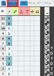
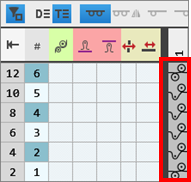
Display of the symbols |
| |||
|
|
|
Display of the drawing canvas for knitting with all needles. | ||
|
|
Display of the drawing canvas for knitting with all needles mirrored.
| |||
|
|
Display of the drawing canvas for knitting in 1x1 technique.
| |||
|
|
Display of the drawing canvas for knitting in 1x1 technique mirrored.
| |||
|
2 |
Display of the template corresponding to the selected type of knitting elements with control columns and drawing canvas | |||
|
3 |
Control |
Tab with all attributes for creating the different knitting element types | ||
|
Design |
Tab with icons for changing / creating design rows | |||
|
Needle Actions / Colors |
Tab with needle actions and the pattern colors | |||


- 4
- Select the Needle Actions / Colors tab.
- 5
- Select the display of
 Technical Rows.
 - 6
- Draw the structure of the new knitting element with needle actions and the desired pattern color into the technical rows.
- The design rows are generated automatically.
- 7
- Define the control column data in the technical rows.
- 8
- If desired, apply the control column data to the design rows with the
 Control Columns button activated.
 - 9
- Check the knitting element regarding the correct structure with the
 Check button.
 - 10
- Save the knitting element.
Create a new, local knitting element:
- A pattern project is created and opened.
- 1
- Select the
 Knitting Elements tab in the Knitting Elements tool window.
 - 2
- Call-up the Generate a new module context menu of the tool window.
- The New Knitting Element dialog box appears.
|
1 |
Name |
Enter the name of the new knitting element. |
|
2 |
Type of Knitting Element |
Selection of the template for the new knitting element
|
|
3 |
Knitting Technique |
Selection of the basic knitting mode for the new knitting element
|
- 3
- Close the dialog box with the OK button.
- The tool window appears with the corresponding template.
|
1 |
Check |
|
Automatically |
The created knitting element are not automatically checked regarding the correct structure. |
|
|
Automatically |
An automatic check is executed regarding the correct structure of the created knitting element. | ||
|
|
Check |
Checking of the created knitting element regarding the correct structure. | ||
|
Design Rows |
|
Control Columns |
Not applying the control column data from the technical rows to the design rows | |
|
|
Control Columns |
Applying the control column data from the technical rows to the design rows | ||
|
| ||||
|
|
Selection |
Get the design symbols for the technical rows in the selected area created. | ||
|
|
| |||
|
|
| |||
|
|
| |||
|
Display of the symbols |
| |||
|
|
|
Display of the drawing canvas for knitting with all needles. | ||
|
|
Display of the drawing canvas for knitting with all needles mirrored.
| |||
|
|
Display of the drawing canvas for knitting in 1x1 technique.
| |||
|
|
Display of the drawing canvas for knitting in 1x1 technique mirrored.
| |||
|
2 |
Display of the template corresponding to the selected type of knitting elements with control columns and drawing canvas | |||
|
3 |
Control |
Tab with all attributes for creating the different knitting element types | ||
|
Design |
Tab with icons for changing / creating design rows | |||
|
Needle Actions / Colors |
Tab with needle actions and the pattern colors | |||
- 4
- Select the Needle Actions / Colors tab.
- 5
- Select the display of Technical Rows.
- 6
- Draw the structure of the new knitting element with needle actions and the desired pattern color into the technical rows.
- The design rows are generated automatically.
- 7
- Define the control column data in the technical rows.
- 8
- If desired, apply the control column data to the design rows with the Control Columns button activated.
- 9
- Check the knitting element regarding the correct structure with the Check button.
- 10
- Close the tool window with X.
- A new local knitting element is saved in the Knitting Elements tab.
Properties of Knitting Elements
The properties define the behavior, the appearance and the size of a knitting element for the use within the pattern project.
Properties Dialog Box:
- 1
- Select module.
- 2
- Open the context menu.
- 3
- Select Properties.
- The Properties dialog box appears.
- 4
- Set the desired properties.
- 5
- Close the dialog box with
 .
.
- The properties are applied when using it in the pattern.
Explaining the Properties dialog box by the Technical Module type of knitting element
|
| ||||
|
1 |
Graphic presentation of the selected type of knitting element | |||
|
2 |
Name |
Name of the knitting element | ||
|
Knitting Technique |
Definition of the knitting technique for the use within the pattern | |||
|
Type of Knitting Element |
Display of the selected type of knitting element
| |||
|
Sub-type of Knitting Elements |
Selection of sub-types according to the selected knitting element type
| |||
|
Knitting Element Color |
Definition of a color for the display of the knitting element in the | |||
|
|
Display color for the different knitting elements or modules | |||
|
|
Display color for structure modules with the different knitting techniques | |||
|
Pattern Rows |
Quantity of pattern rows in the knitting element | |||
|
Technical Rows |
Quantity of technical rows in the knitting element | |||
|
Width [needles] |
Quantity of needles within one row of the knitting element | |||
|
3 |
History |
Display of state of editing from creation until the last modification: Editor Date Version Action | ||
|
4 |
Comment |
Entry of a comment or a description | ||
|
5 |
Control Columns |
Control Column Options
| ||
|
|
Not enabled options suppress the corresponding function in the control columns within the area of this knitting element. | |||
|
|
Selected options enable the corresponding function in the control columns within the area of the knitting element. | |||

 document window with the


Examples for 'Structure Module' Type of Knitting Element
- Example 1: Knitting process with knitting rows only
- Example 2: Knitting process with knitting and not knitting rows
- Knitting Rows: A yarn carrier is used by the knitting system
- Not knitting rows: No yarn carrier is used by the knitting system
(transferring, post loop sinking, casting-off)
Example 1: Create a Structure knitting element with knitting rows only:
- 1
- Open the New Knitting Element dialog box with New Knitting Element.
- or -
Select tool window Modules -> tab Modules -> context menu Generate a new module. - 2
- Enter the name of the new knitting element.
- 3
- Make the following settings:
- Knitting Technique
- All Needles
- Type of Knitting Element :
- Structure Module
- Filling Elements
- No yarn color / magazine color or yarn carrier color
- No Needle Action
- Dimension [stitches]
- Width
- Height
- 4
- Close the dialog box with OK.
- The Knitting Element Editor is opened.
- 5
- Select the Needle Actions / Colors tab.
- 6
- Draw the desired structure with needle actions in the drawing canvas, in the displayed technical rows indicated by .
- The design rows are generated automatically.
|
|
|
 :
:
- 7
- Select for drawing the knitting element:
- Without pattern color
- With pattern color
|
Without pattern colors |
With pattern colors |
|---|---|
|
|
|
|
The needle action has no |
The needle action has an assigned color, i.e. the structure module will be drawn in the design pattern with this color. |
 color, i.e. the structure module can be drawn in the design pattern into every color area.
- 8
- Enter the desired control column data in the corresponding control column of the corresponding technical rows.
- Stitch Length (NP)
- Main Take-down (WMF / WBF)
- Speed (MSEC)
- etc.
|
Entry |
Meaning |
|---|---|
|
Color entry |
Assignment of a parameter value from the corresponding table |
|
No color entry |
Standard entry from the design pattern is kept |
- 9
-
Design Rows
:
Enable the Control Columns button to apply the control column data from the technical rows to the design rows.
Behavior of control column data
|
No control column data |
Control column data in technical rows only |
Control column data in technical rows and design rows |
|---|---|---|
|
|
|
|
|
With drawing in the design pattern and with the technical processing, no entry is made in the control columns. |
These data from the technical rows will be inserted by the technical processing if in advance the standard entry is manually removed from the desired control columns of the design pattern. |
When drawing in the design pattern it can be decided whether the control column data are to be entered in the design rows with the help of the cursor attributes.
|
- 1
- Check the formal correctness of the entries in the knitting element with the Check: button.: The knitting procedure cannot be checked!
- 2
- If necessary, in case of a knitting element already used in the design pattern, apply the changes to the basic pattern with the
 Apply button.
 - 3
- Close the New Knitting Element tool window with .
- The knitting element is saved.
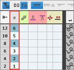
Group the pattern rows in the knitting element:
Group the technical rows which you want to form a common pattern row.
- A knitting element with multiple technical rows is created.: Each technical row corresponds to one design row.
- 1
- Select the desired technical rows.
- 2
- Position the cursor on the first control column, open the context menu and select Group Rows.
- or -
Group the selected technical rows with Ctrl + G.
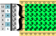
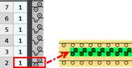
Behavior when drawing in the design pattern
|
|
|
|
All pattern rows are drawn-in one-to-one in the design pattern. This means that the corresponding number of pattern rows will be overwritten in the design pattern. |
|
|
|
|
When drawing, only the first technical row is drawn in the design pattern. This means that the remaining technical rows of the group will be additionally inserted in the pattern by the technical processing. |


Ungroup the rows:
- In the knitting element the technical rows are grouped.
- 3
- Select the desired technical rows.
- 4
- Position the cursor on the first control column, open the context menu, select Ungroup Rows.
- or -
Cancel the selection of the technical rows by Ctrl + Shift + G.
: If necessary, repeat the process multiple times.
Variants:
- All needles knit

- All needles knit mirrored

- 1x1 Technique

-
 1x1 Technique, Mirrored
Procedure:
- A variant is created.
- 1
- Position the cursor in the drawing canvas.
- 2
- Open the context menu with RMB.
- 3
- Select Create Variant.
- 4
- Select the variant to be created in the submenu.
- The created variant is displayed in the drawing canvas.
- 5
- If desired, make changes in the technical rows and in the control column data of the new variant.
Not knitting rows are:
- Transferring rows.
- Casting-off rows
- Rows for post loop sinking
Creating structure module with knitting and not knitting rows:
- 1
- Open the New Knitting Element dialog box with New Knitting Element.
- or -
Select tool window Modules -> tab Modules -> context menu Generate a new module. - 2
- Enter the name of the new knitting element.
- 3
- Make the following settings:
- Knitting Technique
- All Needles
- Type of Knitting Element :
- Structure Module
- Filling Elements
- No yarn color / magazine color or yarn carrier color
- No Needle Action
- Dimension [stitches]
- Width
- Height
- 4
- Close the dialog box with OK.
- The Knitting Element Editor is opened.
- 5
- Select the Needle Actions / Colors tab.
- 6
- In the drawing canvas, in the technical rows, draw the desired structure with knitting and e.g. transfer needle actions.
- The design rows are generated automatically.
- 7
- If necessary, select a color for drawing.
- 8
- Enter the desired control column data in the corresponding control column of the corresponding technical rows with needle actions.
- Stitch Length (NP)
- Main Take-down (WMF / WBF)
- Speed (MSEC)
- etc.
- 9
- Also enter the desired control column data in the transfer rows:
-
Racking (VN, VU, V#)

-
Racking Value

- Racking Correction (VCI)
- Main Take-down (WMF)
- etc.
- 10
- Select transfer rows with the previous knitting row or with following knitting row.
- 11
- Group the selected rows with the CTRL + G keys.
|
|
|

- 12
-
Design Rows:
Enable the Control Columns button to apply the control column data from the technical rows to the design rows. - 13
- Check the correctness of the entries in the knitting element with the Check: button.: The knitting procedure cannot be checked!
- 14
- If necessary, in case of a knitting element already used in the design pattern, apply the changes to the basic pattern with the Apply button.
- 15
- Close the New Knitting Element tool window with .
- The knitting element is saved.
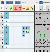
Change / reset design rows
When creating a knitting element, the design rows are generated automatically. It is possible to change the design rows manually.
Changing design rows manually:
- The knitting element is created.
- Design rows were generated automatically.
- 1
- Open knitting element with double-click.
- 2
- Activate the display of the design rows with the
 button.
 - 3
- Select the Design tab in the tool window.
- All symbols that may be used in the design rows are shown in this tab.
- 4
- Select the desired symbol.
- 5
- Draw the symbol in the corresponding design row.
- 6
- If necessary, continue with more design rows.
- 7
- Knitting Element with .
- The change is saved and marked with the M symbol (modified).
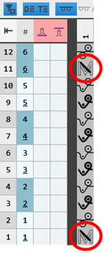
Reset: Delete the M symbol in the modified design row:
- In the knitting element, there are design rows marked with the M symbol.
- 8
- Select one or more design rows.
- 9
- Click the
 Calculate Design Symbols button in the tool window.
- The M symbol is deleted and the symbol of the corresponding technical row is applied automatically.