Change the shape in the M1plus Shape Editor
You can use the default shapes in the Shape folder as basis and adjust them to your own needs.
I. Changing the basic shape element:
- 1
- Call up the M1plus Shape Editor via / .
- 2
- Open an existing shape via the / menu.
- or -
Click .
.
- The Open dialog box will be displayed.
- 3
- Enter the path for the desired Form folder (with default shapes).
D:\ Stoll \ M1plus \ <Version number> \ Shape \... - 4
- Select the desired shape in *shv.
Example: 3_set-in-I-round-front-r-neck-38.shv - 5
- Convert the opened shape into the *.shp format via the / menu.
- 6
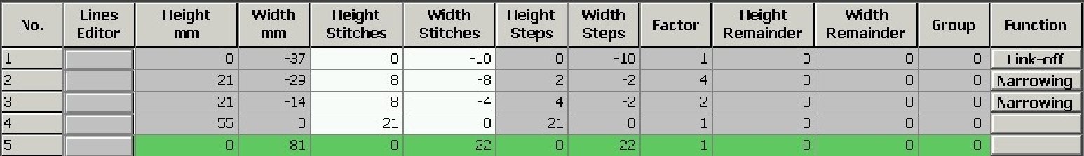
- Change the outer edge of the front:
- Line 3: Change narrowing at the sleeve cut-out to binding-off.
- Delete possible existing lines.
Basic element Front:
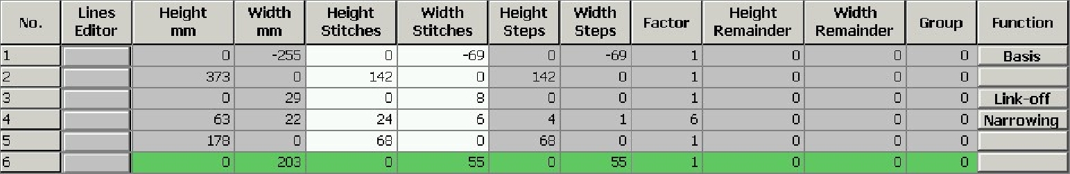
- 7
- Click on Narrowing in line no. 3 under .
- The dialog box with the tabs will be opened.
- 8
- Select Binding-off via the selection list of the Function column in the tab.
- The Binding-off tab becomes active.
- 9
- Open the Binding-off tab and select the desired binding-off method in the selecting list:
- BO-SJ-01
- BO-SJ-02
- 10
- Confirm settings with OK.
- The dialog box is closed.
II. Modify the neck opening element:
- 1
- Select the neck opening element in the M1plus Shape Editor.
- The table for Left lines is displayed.
- 2
- Modify the element:
Neckline Element
- 3
- Click on in the line no. 1 of the Function column.
- The dialog box with the tabs will be opened.
- 4
- Open the tab and select Cut-out Neck bottom Centre under function in the selection list.
- 5
- Allocate the starting module Structure single jersey V2 from the Module Explorer of Database to the corresponding knitting mode with drag & drop
 .
. - 6
- Position the start module by the settings under .
 has to be deactivated for positioning the starting module.
- 7
- Save the shape via the / or menu.
- The shape will be saved in the shp format.
III. Possibilities when binding-off:
Binding-off is directional!
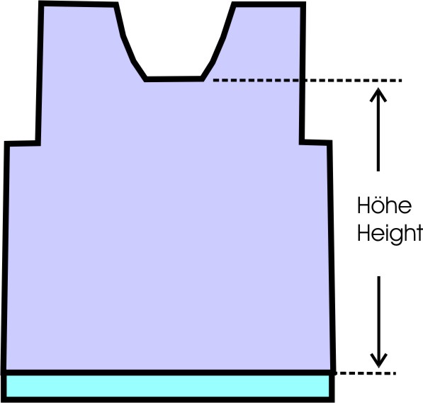
Height up to the beginning of the neck opening:
- The height has to be an even number if the binding-off is to be carried out from left to right in the carriage stroke.
- The height has to be an odd number to binding-off from right to left in the carriage stroke.
The position of the neck opening element is affected by:
- the total height of the basic shape element.
- the total height of the neck opening element.
- the positioning of the neck opening element.
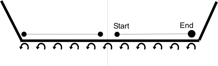
Positioning of the starting module in the neck opening element:
|
Binding-off |
Carriage direction |
Position |
|---|---|---|
|
|
to the left |
Right edge: |
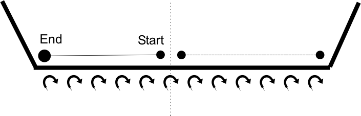
|
|
to the right |
Left edge: |
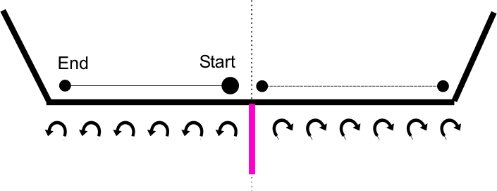
|
|
To the right and to the left |
Left edge: |