Generate a Module Arrangement
Generate a Module Arrangement from a selection:
- A shaped pattern
 is load after the Cutting out step of processing.
- 1
- Click on
 and
and  of the Pattern Presentation k&w toolbar.
- The suspending rows and the aligning symbols will be hidden in the Symbol View [Basic with shape].
- 2
- Draw in different structure modules on the same row:
- Of front layer (L0) only: Adjustment of the module from L0 only
- Of back layer (L1) only: Adjustment of the module from L1 only
- Of both layers (L0 + L1): Adjustment of the modules from L0, from L1 and from L0 in relation to L1
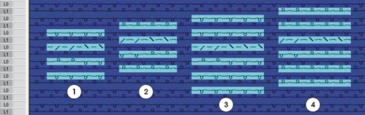
Excample with modules on both layer:
|
|
Designation |
|---|---|
|
1 |
Cable 2x2 on front layer (L0) |
|
2 |
Cable 2x2 on back layer (L1) |
|
3 |
Cable 3x2 on front layer (L0) |
|
4 |
Cable 3x2 on back layer (L1) |
- 3
- Select the pattern rows with modules.
Only modules of the same knitting row can be arranged to each other.
- 4
- Click the
 icon in the Default toolbar.
- or -
Call up the / / menu.
- All modules existing in the selection are displayed in the Module Arrangement Editor.
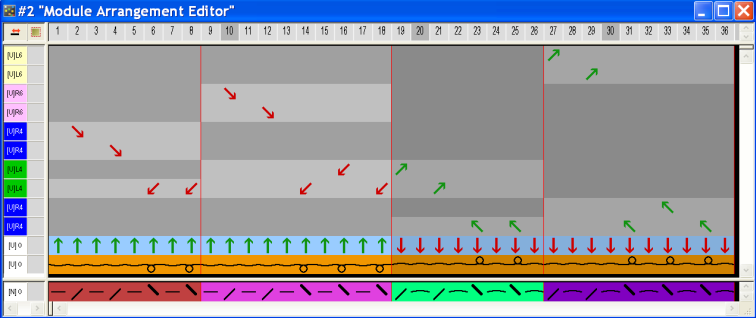
The settings in the / menu initially determine the racking priority in the Module Arrangement.
- 5
- Click the Aligning
 icon in the Drawing tools toolbar.
 - 6
- Activate the desired options in the Tool Properties dialog box.
- 7
- Modify the Module Arrangement.
- 8
- Close the Module Arrangement Editor with
 .
.
- The prompt appears.
- 9
- Confirm the query with Yes.
- The color marking of the Module Arrangement will automatically be entered in the control column of the selected pattern area.
The Module Arrangement will be saved with the pattern and can be selected in the tab of the Module toolbar.