Modify a Shape in the Symbol View [Basic].
I. Correct a shape in the symbol view [Basic]
- 1
- Present the positioned (shv / shp / shr) shape in the Symbol View [Basic].
- The icons in the Pattern Presentations toolbar get active.
|
|
Presentation |
|---|---|
|
|
Display shape edges. |
|
|
Display shape symbols. |
|
|
You can activate these icons to get the desired presentation of the basic pattern.
|


 :
:- 2
- Activate
 and
and  in the Symbol View [Basic].
 - 3
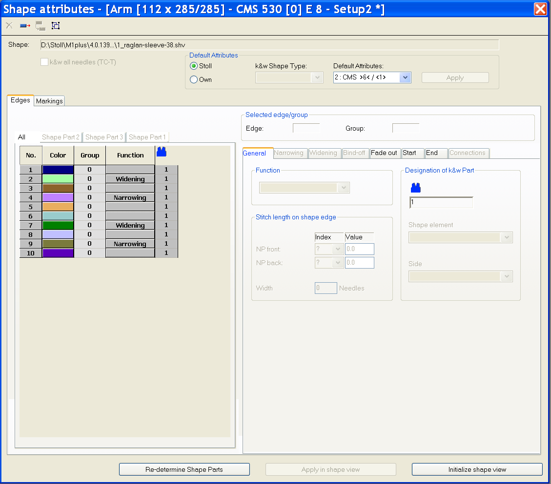
- Call up the context menu of the Symbol View [Basic with Shape].
- The dialog box will be opened.
- 4
- Select the desired shape edge color in the of the Shape Attributes dialog box.
- or -
Pick the shape edge color in the Basic Pattern with or the F6 key.
 - 5
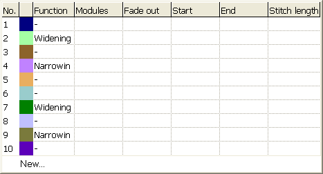
- Select the drawing tool and symbol from Shape Attributes.
Shape attributes toolbar


|
Function |
Meaning | |
|---|---|---|
|
|
Outside Shape |
Editing areas not belonging to the shape. |
|
|
Shape Part Color (within shape): <No.> |
Allocate a shape part color to a shape part |
|
|
Edge: <No.> |
Allocate an edge color to an edge. |
|
|
Marks: <No.> |
Allocate shape marking |
|
|
Goring |
Draw-in or change gore areas |
|
|
Narrow / Widen |
Draw-in the symbol Narrow / Widen in the shape edge. |
|
|
Fading-out |
Draw fade-out symbol in the shape edge. |
|
|
Separation |
Edit the automatically generated separation. |
|
|
Binding-off |
Draw binding-off symbol in the shape edge. |
|
|
Stitch length change |
Draw-in the symbol Stitch length change (PTS) in the shape edge. |
|
|
Aligning within Shape Part to the Left |
Enter aligning symbols within a shape. The area on the right of the symbol will be moved to the left. |
|
|
Aligning within Shape Part to the Right |
Enter aligning symbols within a shape. The area on the left of the symbol will be moved to the right.
|
|
|
Align to the left |
Enter aligning symbols to the left. The shape part will be moved to the right. |
|
|
Align to the right |
Enter aligning symbols to the right. The shape part will be moved to the left. |
|
|
Suspending to bottom |
Enlarge the area for the suspension with knit and wear shapes downwards |
|
|
Suspending to top |
Enlarge the area for the suspension with knit and wear shapes upwards |
|
|
Place border marking on the left |
Symbol for border marking at the shape edge at the left
|
|
|
Place border marking on the right |
Symbol for border marking at the shape edge at the right
|
|
|
Multi-step Narrowing |
Draw-in symbol for multi-step narrowing Narrowing underneath |
|
|
Multi-step Narrowing |
Draw-in symbol for multi-step narrowing Narrowing above |
|
|
Selection menu |
Specification of the racking step (cover width) for multi-step narrowing |
|
|
Remove single shape attributes |
Delete the shape attribute drawn-in. Select the shape symbol (e.g. |
|
|
Remove all shape attributes |
Delete all drawn-in shape attributes and edge colors. |
 .
.- 6
- Correct the shape edge with the selected shape attributes.
You can pick shape attributes with the F7 key.
- 7
- Activate in the context menu.
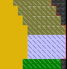
- The red outlines along the shape edges will be displayed.
The reference edges (outlines) are helpful when changing the shape since the deviations from the original shape are displayed.
- 8
- Correct the selected shape edge:
- Outer edge shape
- Fading-out
- Narrow / Widen
Before the correction:
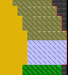
- 9
- Call up the context menu.
- The red outlines will be adjusted to the new outer edge.
After the correction:
II. Creating a new shape edge:
- 1
- Display the shape edge colors with and the shape attributes with in the Symbol View [Basic] with the shape loaded.
- 2
- Call up the Shape Attributes... context menu of the .
- or -
Open the selection list in the Shape Attributes toolbar with and select .
- The Shape attributes dialog box is opened.
- 3
- Press the
 icon (1) in the Shape Attributes dialog box.
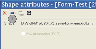
- A new shape edge is generated.
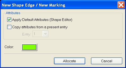
- 4
- Select the desired settings in the New Shape Edge / New Marking dialog box.
|
Check box |
Meaning | ||
|---|---|---|---|
|
|
A new edge color is created with Stoll standard attributes.
| ||
|
|
A new edge color will be created with the attributes of the selected edge number.
| ||
|
|
Entry |
|
Selection of the edge number as source of attributes. |

- 5
- Add the new edge color in the table with the Allocate button in the New Shape Edge / New Marking dialog box.
III. Apply the new shape edge:
- 1
- Select the new shape edge in the Shape Attributes dialog box.
- or -
Open the selection list in the Shape Attributes toolbar with and select a shape edge. - 2
- Select the desired shape attribute with the Ctrl key pressed in the Shape Attributes toolbar additionally.
- 3
- Draw in the new shape edge with the selected shape attribute into the basic pattern.
- 4
- Allocate shape part color 1 to the shape edge color with the Re-determine Shape Parts button.
- 5
- Call up the context menu with the right mouse button below the table of edge colors in the Shape Attributes dialog box:
- Change Color
- Delete shape edges not used.
- 6
- Click on the button
 in the Shape Attributes dialog box.
- The settings will be saved and the Shape Attributes dialog box will be closed.
Buttons in the Shape Attributes dialog box:
|
Button |
Meaning |
|---|---|
|
Re-determine the shape parts |
The shape parts / shape part colors will be re-determined. |
|
Apply in shape view |
Only the changes in the Shape attributes are applied in the Symbol View (with shape). |
|
Initialize shape view |
All entries in Shape attributes are applied in the Symbol View (with shape) and saved. |
IV. Stitch length on shape edge:
- 1
- Select the desired shape edge in the Shape Attributes dialog box.
- 2
- Select tab.
- 3
- Make the desired settings in the section:
|
|
Index |
Value |
|---|---|---|
|
NP front: |
Select NP index |
NPEnter value |
|
NP rear: |
Select NP index |
NPEnter value |
|
Width |
Enter the quantity of needles for PTS at the shape edge
| |
- 4
- Carry out the
 processing step.
- In the Configuration dialog box
 is automatically active.
- 5
- Call up the tab in the Configuration dialog box.
- 6
- Make settings in the Variable stitch length section if necessary:
|
Variable stitch length on shape edge | ||
|---|---|---|
|
NPJ: . = |
Enter value |
|
|
Carriage speed for NPJ (MSECNPJ) | ||
|
|
Machine speed MSEC =1.0 | |
|
|
Machine speed MSEC according to specification | |

When using PTS / NPJ the adjusting and idle times are to be observed.